The sudden unintended acceleration problems in Toyota’s vehicles have touched off a firestorm of controversy over the cause(s). Accusations of problems with the electronics throttle system were quickly followed by emphatic denials by the automaker. Then on Feb. 23, Toyota’s top US executive testified under oath before US Congress that the automaker had not ruled out electronics as a source of the problems plaguing the company’s vehicles. Subsequently, other company officials denied that was true.
To confuse matters more, a professor of automotive technology claims to have found a flaw in the electronics system of no fewer than four Toyota models that “would allow abnormalities to occur.” Testifying before Congress, David W. Gilbert, a Ph.D. with almost 30 years’ experience in automotive diagnostics and troubleshooting, said the trouble locating the problem’s source could stem from a missing defect code in the affected fleet’s diagnostic computer.
Prof. Gilbert said his initial investigation found problems with the “integrity and consistency” of Toyota’s electronic control modules to detect potential throttle malfunctions. Specifically, Prof. Gilbert disputed the notion that every defect would necessarily have an associated code. The “absence of a stored diagnostic trouble code in the vehicle’s computer is no guarantee that a problem does not exist.” Finding the flaw took about 3.5 hours, he added. (A video of Prof. Gilbert’s test at his university test track is at www.snotr.com/video/4009.)
It took two weeks for the company to strike back. In early March, Toyota claimed Prof. Gilbert’s testimony (http://circuitsassembly.com/blog/wp-content/uploads/2010/03/Gilbert.Testimony.pdf) on sudden unintended acceleration wasn’t representative of real world situations. In doing so however – and this is important – Toyota made no mention (at least in its report) about Prof. Gilbert’s more important finding: the absence of the defect code. Was Toyota’s failure to address that an oversight? Or misdirection?
Second in concern only to the rising death toll is Toyota’s disingenuous approach to its detractors. Those who follow my blog realize I’ve been harping on this for several weeks. But why, some readers have asked.
The reason is subtle. Electronics manufacturing rarely makes international headlines, and when it does, it’s almost always for the wrong reasons: alleged worker abuses, product failures, (mis)handling of potentially toxic materials, and so on. The unfolding Toyota story is no different.
Yet it’s important the industry get ahead of this one. Planes go down over oceans and their black boxes lost to the sea. Were the failures brought about by conflicts between the cockpit navigational gear and on-board satellite entertainment systems? When cars suddenly accelerate, imperiling their occupants, was it a short caused by tin whiskers that left the driver helpless? It’s vital we find out.
In the past four years, NASA’s Goddard Space Flight Center, perhaps the world’s premiere investigator of tin whiskers, has been contacted by no fewer than seven major automotive electronics suppliers inquiring about failures in their products caused by tin whiskers. (Toyota reportedly is not one of them, but word is NASA will investigate the incidents on behalf of the US government.) These are difficult, painful questions, but they must be examined, answered, and the results disseminated. Stonewalling and misdirection only heighten the anxiety and fuel accusations of a cover-up.
We as an industry so rarely get the opportunity to define just how exceedingly difficult it is to build a device that works, out of the box, as intended, every time. A Toyota Highlander owner has a satellite TV monitor installed into his dash, then finds certain controls no longer work as designed. A Prius driver’s car doesn’t start when he’s using his Blackberry. It’s impossible for an automotive company to predict and design for every single potential environmental conflict their models may encounter.
The transition to lead-free electronics has been expensive and painful for everyone – even for those exempt by law, because of the massive infiltration of unleaded parts in the supply chain. And despite no legal impetus to do so, some auto OEMs have switched to lead-free. Moreover, to save development time costs, automakers are quickly moving to common platforms for entire fleets of vehicles, dramatically exacerbating the breadth of a defect. We do not yet know if lead-free electronics is playing a role in these catastrophic failures. But if tin whiskers or some other electronics-related defect are the cause, or even a cause, of these problems, we need to know. If we are inadvertently designing EMC in, we need to know.
Toyota’s PR disaster could be a once-in-a-lifetime chance for the electronics industry to reposition itself. What we build is important and life-changing. This is a chance to take back our supply chains from those whose single purpose is cost reduction, and to redefine high-reliability electronics as a product worth its premium. And it’s a chance to explore whether wholesale industry changes are conducted for the good of the consumer, or for short-term political gain. It’s a tragic reminder that science, not opinion, must always win, and that moving slowly but surely is the only acceptable pace when designing and building life-critical product.
‘Virtually’ great. A big “thank you” to the 2,600-plus registrants of this year’s Virtual PCB conference and exhibition. It was the best year yet for the three-year-old show, confirming once again that there’s more than one way for the industry to get together. The show is available on-demand through May 4; be sure to check it out at virtual-pcb.com.
Setting up the proper feedback loop saves time and cost in re-spins.
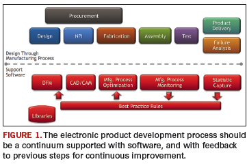
When considering electronics product development, design and manufacturing often are thought of as separate processes, with some interdependencies. The processes seldom are considered as a continuum, and rarely as a single process with a feedback loop. But the latter is how development should be considered for the purposes of making competitive, fast-to-market, and lowest cost product.
Figure 1 shows the product development process from design through manufacturing to product delivery. This often is a segmented process, with data exchange and technical barriers between the various steps. These barriers are being eliminated and the process made more productive by software that provides for better consideration of manufacturing in the design step, more complete and consistent transfer of data from design to manufacturing, manufacturing floor optimization, and the ability to capture failure causes and correct the line to achieve maximum yields. The goal is to relay the failure causes as improved, best-practice DfM rules and prevent failures from happening.
The process starts with a change in thinking about when to consider manufacturing. Design for manufacturability should start at the beginning of the design (schematic entry) and continue through the entire design process. The first step is to have a library of proven parts, both schematic symbols and component geometries. This forms the base for quality schematic and physical design.
Then, during schematic entry, DfM requires communication between the designer and the rest of the supply chain, including procurement, assembly, and test through a bill of materials (BoM). Supply chain members can determine if the parts can be procured in the volumes necessary and at target costs. Can the parts be automatically assembled or would additional costs and time be required for manual operations? Can these parts be tested using the manufacturer’s test equipment? After these reviews, feedback to the designer can prevent either a redesign or additional product cost in manufacturing.
The next DfM is to ensure the layout can be fabricated, assembled and tested. Board fabricators do not just accept designer data and go straight to manufacturing. Instead, fabricators always run their “golden” software and fabrication rules against the data to ensure they will produce boards that are not hard failures, and to determine adjustments to avoid soft failures that could decrease production yields.
So, for the PCB designer, part of the DfM is to use this same set of golden software and rules often throughout the design process. This practice not only could prevent design data from being returned from the fabricator or assembler, but, if used throughout the process, could ensure that design progress is always forward, with no redesign necessary.
A second element in this DfM process is the use of a golden parts library to facilitate the software checks. This library contains information typically not found in a company’s central component libraries, but rather additional information specifically targeted at improving a PCB’s manufacturability. (More on this later.)
When manufacturing is considered during the design process, progress already has been made toward accelerating new product introduction and optimizing line processes. Design for fabrication, assembly and test, when considered throughout the design function, helps prevent the manufacturer from having to drastically change the design data or send it back to the designer for re-spin. Next, a smooth transition from design to manufacturing is needed.
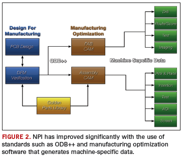
As seen in Figure 2, ODB++ is an industry standard for transferring data from design to manufacturing. This standard, coupled with specialized software in the manufacturing environment, serves to replace the need for every PCB design system to directly produce data in the formats of the target manufacturing machines.
Time was, design systems had to deliver Gerber, machine-specific data for drill, pick-and-place, test, etc. Through standard data formats such ODB++ (and other standards such as GenCAM), and available fab and assembly optimization software, the manufacturing engineers’ expertise can be capitalized on. One area is bare board fabrication. If the designer has run the same set of golden rules against the design, there is a good chance no changes would be required, except ones that might increase yields. This might involve the manufacturer spreading traces, or adjusting stencils or pad sizes. But the risk here is the manufacturer does not understand tight tolerance rules and affects product performance. For example, with the emerging SERDES interconnect routing that supports data speeds up to 10 Gbs, matching trace lengths can be down to 0.001˝ tolerance. Spreading traces might violate these tolerances. It is important the OEM communicate these restrictions to the manufacturer.
From an assembly point of view, the manufacturer will compare received data (pad data and BoM) to a golden component library. Production engineers rely on this golden library to help identity BoM errors and footprint, or land pattern mismatches prior to first run. For example, the actual component geometries taken from manufacturer part numbers in the BoM are compared to the CAD footprints to validate correct pin-to-pad placement. Pin-to-pad errors could be due to a component selection error in the customer BoM. Although subtle pin-to-pad errors may not prevent parts from soldering, they could lead to long-term reliability problems.
Designers have DfT software that runs within the design environment and can place test points to accommodate target testers and fixture rules. Final test of the assembled board often creates a more complex challenge and usually requires a manufacturing test engineer to define and implement the test strategy. Methods such as in-circuit or flying probe testing require knowledge of test probes, an accurate physical model of the assembly (to avoid probe/component collisions), and the required test patterns for the devices.
Manufacturing Process Optimization
Even as a new assembly line is configured in preparation for future cost-efficient production, for high-mix, high-volume or both, simulation software can aid in this process. Many manufacturers are utilizing this software to simulate various line configurations combined with different product volumes and/or product mixes. The result is an accurate “what if?” simulation that allows process engineers to try various machine types, feeder capacities and line configurations to find the best machine mix and layout. Using line configuration tools, line balancers, and cycle time-simulators, a variety of machine platforms can be reviewed. Once the line is set up, this same software maintains an internal model of each line for future design-specific or process-specific assembly operations.
This has immediate benefits. When the product design data are received, creating optimized machine-ready programs for any of the line configurations in the factory, including mixed platforms, can be streamlined. A key to making this possible lies in receiving accurate component shape geometries, which have been checked and imported from the golden parts library. Using these accurate shapes, in concert with a fine-tuned rule set for each machine, the software auto-generates the complete machine-ready library of parts data offline, for all machines in the line capable of placing the part. This permits optimal line balancing, since any missing part data on this or that machine – which can severely limit an attempt to balance – are eliminated. The process makes it possible to run new products quickly because missing machine library data are no longer an issue. Auto-generating part data capability also makes it possible to quickly move a product from one line to another, offering production flexibility.
Programming the automated optical inspection equipment can be time-consuming. If the complete product data model – including all fiducials, component rotations, component shape, pin centroids, body centroids, part numbers (including internal, customer and manufacturer part numbers), pin one locations, and polarity status – is prepared by assembly engineering, the product data model is sufficiently neutralized so that each different AOI platform can be programmed from a single standardized output file. This creates efficiency since a single centralized product data model is available to support assembly, inspection and test.
Managing the assembly line. Setting up and monitoring the running assembly line is a complex process, but can be greatly improved with the right software support. Below is a list of just a few elements to this complex process:
Registering and labeling materials to capture data such as reel quantity, PN, date code and MSD status.
Streamlining material preparation and kitting area per schedule requirements, plus real-time shop floor demand, including dropped parts, scrap and MSD constraints.
Feeder trolley setup (correct materials on trolleys).
Assembly machine feeder setup, verification and splicing.
Manual assembly, and correct parts on workstations.
Station monitoring, capture runtime statistics, efficiency, feeder and placement errors and OEE calculations.
Call for materials to avoid downtimes.
Tracking and controlling production work orders to ensure visibility throughout the process.
Enforcing the correct process sequence is followed, and any test or inspection failure is corrected to “passed” status before product proceeds.
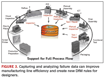
Collecting failure data. It is inevitable some parts will fail. By capturing and analyzing these data, causes can be determined and corrected. Figure 3 shows certain areas where failures are diagnosed and collected using software. One benefit of software is the ability to relate, in real-time, test or inspection failures with the specific machine and process parameters used in assembly and the specific material vendors and lot codes used in the exact failure locations on the PCB.
Earlier, a set of DfM rules in the PCB design environment that reflects the hard and soft constraints to be followed by the designer was discussed. If these rules were followed, we could ensure that once design data reached manufacturing, they would be correct and not require a redesign. What we did not anticipate was that producing a product at the lowest cost and with the most efficiency is a learning process. We can learn by actually manufacturing this or similar designs, and determine what additional practices might be applied to DfM to incrementally improve the processes.
This is where the first feedback loop might help. If we capture data during the manufacturing process and during product failure analysis, this information can be used to improve DfM rule effectiveness. Continuous improvement of the DfM rule set based on actual results can positively influence future designs or even current product yields.
The second opportunity for feedback is in the manufacturing process. As failures are captured and analyzed (Figure 3), immediate feedback and change suggestions can be sent to the processing line or original process data models. Highly automated software support can reconfigure the line to adjust to the changes. For example, software can identity which unique machine feeder is causing dropped parts during placement. In addition, an increase in placement offsets detected by AOI can be immediately correlated to the machine that placed the part, or the stencil that applied the paste, to determine which tool or machine is in need of calibration or replacement. Without software, it would be impossible to detect and correlate this type of data early enough to prevent yield loss, rework or scrapped material.
Design through manufacturing should be treated as a continuum. One starts with the manufacturer’s DfM rules, followed and checked by the designer’s software, the complete transfer of data to the manufacturer using industry-recognized standards, the automated setup and optimization of the production line, the real-time monitoring and visibility of equipment, process and material performance, and finally the capture, analysis and correlation of all failure data. But the process does not end with product delivery, or even after the sale support. The idea of continuum is that there is no end. By capturing information from the shop floor, we can feed that to previous steps (including design) to cut unnecessary costs and produce more competitive products.
John Isaac is director of market development at Mentor Graphics (mentor.com); This email address is being protected from spambots. You need JavaScript enabled to view it.. Bruce Isbell is senior strategic marketing manager, Valor Computerized Systems (valor.com).
Ed.: At press time, Mentor Graphics had just completed its acquisition of Valor.
Bringing tutorial-level instruction to designers’ desktops.
Last month UP Media Group produced our third Virtual PCB trade show and conference for PCB design, fabrication and assembly professionals. Every year the event has grown and shown more promise as a format for bringing together the industry.
We originally started researching virtual trade shows in the late 1990s, but the technology was just not ready. There just was no platform for doing a virtual show in a way that we felt would appeal to our audience.
About four years ago, things changed. Editor-in-chief Mike Buetow called our attention to a company that had a good grasp of what we needed. For those of you who don’t know Mike, he is a thorough and hard-charging editor, with a good handle on most areas of the fabrication and assembly sides of the printed circuit board market. Once Mike set us on the path, UPMG’s Frances Stewart and Alyson Skarbek turned the concept of Virtual PCB into a must-attend event. This year we had a record registration of over 2,600 people from literally every corner of the globe. Those who missed the two-day live event can view the on-demand version, available through May 4.
I take this as another indicator of the power of the Internet. And though we at UPMG are, at heart, print kind of people, we realize the Internet has a huge and still-evolving role to play in how we interact with our readers and advertisers.
This leads me to our latest project. The PCB Design Conferences have always been one of my favorite projects. As an old PCB designer at heart, I realized from my own experience how much we need to learn about every aspect of design, and to stay in touch with technology that sometimes changes almost daily. A couple months ago, a friend turned me on to a software platform that allows us to take the virtual experience to a new level. This new project is called Printed Circuit University. PCU’s primary mission is to help PCB designers, engineers and management stay abreast of technology and techniques. We’ll accomplish this through short flash presentations, webinars, white papers, resource links and blogs by some of the most interesting people in the industry. You’ll be able to post questions for peers to comment, and share experiences and opinions on just about any subject that has to do with circuit boards.
Then there is the Design Excellence Curriculum. The DEC is a program we developed around 15 years ago for the PCB Design Conference. Over the years, thousands of PCB designers and engineers have taken the courses and furthered their knowledge of specific areas of PCB design. Today, the Web allows us to reach a greater number of people than ever, so we’ve decided to bring the DEC to Printed Circuit University.
How does it work? Think of a college curriculum where to get a degree in a specific subject you complete core classes like English and math that round out your general knowledge, and then follow a field of study that builds knowledge in the area you want to pursue. Core classes are on subjects that build the foundation for what every good designer should know: PCB fabrication, assembly and test; dimensioning and tolerances; laminates and substrates; electrical concepts of PCBs.
After passing the core courses, you’ll be able to choose from a series of classes on specific subjects such as flex design, signal integrity, RF design, advanced manufacturing, packaging and a host of others designed to build your knowledge in that area. After the core classes, a person can study as many fields as they want, to gain more and more knowledge of all types of PCB design.
The platform we’ve settled on for PCU is the same used by universities and online learning institutions such as Penn State, Tennessee Tech, University of Iowa and many more. The platform establishes a real-time, online classroom where you can see the instructor and ask questions. You’ll be able to view presentation materials, and the instructor can even switch to a white board view to illustrate a point. Sessions will be archived for review at any time, and when you have completed a course of study, you’ll take an exam to demonstrate that you were listening in “class.”
We expect to launch Printed Circuit University at the end of June, so stay tuned. If you have comments or questions, please email me. In the meantime, stay in touch and we’ll do the same.
Pete Waddell is design technical editor of PCD&F (pcdandf.com); This email address is being protected from spambots. You need JavaScript enabled to view it..
When personality enters the equation, process management seems to vanish.
Some things just seem to get to me, and one is the concept of “process management.” It’s not that I don’t like or believe in it. Over the years I have spent tons of money successfully working to improve processes, and have seen firsthand the benefit improved process management can yield. There really is a solid return on investment when improvements are made and productivity improves.
But what gets me is that process management seems to only matter when applied to “things” vs. “people.”
Everyone – regardless of industry or job function – loves to tout improvements derived from applying a process improvement to a “thing.” This may include manufacturing equipment – hardware or software – end-products – newly developed or longstanding favorites – and even bricks and mortar (or elimination of same). However, when the process that needs improvement exclusively involves personnel, and someone’s name is identified with said “process improvement,” watch everyone shy away.
By identifying names, I am referring to when the process improvement involves people who work with people (versus equipment), and when the processes that those people should be developing or following are associated with a small number of colleagues, which means those involved are easily identified. Usually, those people work in externally focused departments (sales, purchasing, administrative functions such as HR and accounts payable and receivable). The process management challenge is to improve the level of service, support or value-add that would create a solid relationship in processes that have heavy interpersonal versus machine-driven interaction. And it is not just the supplier/customer relationship. In any situation that involves people – supplier, customer, consultant, employee – friend or foe – when personality enters the equation, process management seems to vanish.
Some examples: When someone evaluates a plating process and comes up with an optimal chemistry, preferred timing and sequence, or improved equipment or configuration, they tout their process management skills and the resulting improvement as a major victory. However, when dealing with the timing and sequence of involving people in, say, periodic capability updates with customers, or the frequency and “configuration” of communication between key suppliers and purchasing, or even just being more visible with key decision-makers at specific customers or suppliers, those involved often shy away from dealing with the situation. Far worse is if there is a problem, almost everyone will assume the ostrich position: put their head in the sand and hope no one notices the deafening silence caused by a lack of process or management.
This is not to say initiatives don’t take place in people-driven processes. But too often these efforts manifest themselves as software-focused “interfaces” or “portals” – to create a cyber impression of involvement and progressive process management so to improve how people are dealt with – without actually helping the managers tasked with dealing with those people. Others will periodically take momentary actions of heroic brilliance led by an employee who tries to assist. Yet, if the action is not embraced with appropriate reward and recognition, and then adopted and implemented as a true process improvement, then it is not truly process management.
When process improvement exclusively involves people, rather than focusing on process improvement, we tend to deal with only the most serious problems, and even then not in the context of process improvement, but in a superficial, expeditious way.
Using the most basic definition, we are all job shops that cannot create demand or inventory product for future customers, but must react to customers’ specific technological as well as volume needs, responding only when they want it. What differentiates us all – for better or worse – is the level of support and service we offer; the relationships we have with our suppliers, and our abilities to pull together diverse subcontract capabilities to satisfy a pressing customer need. In short, what differentiates us is our ability to interact with … people.
And yet, we tend to not focus as much on process improvement in the very areas that could and will best differentiate us. Yes, cutting-edge software or web portals may help, but do they really address what customers want? We might have the most technologically savvy staffs, but if they don’t want – or know how – to interact with customers consistently and effectively, what is their use? We may be able to identify customers’ or suppliers’ problems, but if we explicitly or implicitly cop an attitude that communicates that we are not the ones who should help, how can our role be viewed as value-add?
While most companies have undergone extraordinary measures to improve internal design and manufacturing process management, I would bet that if the folks at ISO really focused on processes that involve suppliers and customers, most companies would not qualify for certification. Which brings me to the importance of embracing all the processes that link your company with the people to which you are most trying to provide value: customers. Only by making sure you apply the best available processes and people management so you are consistent in how well you treat all the related people – suppliers through customers – can you begin to focus on providing the value-adding process management they all seek.
Disney and Apple seem to get this. Disney parks are consistent in their customer focus and process management to make sure that all customers (“guests”) feel they had the best experience and received the greatest value for their money. Ditto with Apple; its retail stores emphasize service, support and the total “Apple” experience, and hence, the value-add of buying its products and much of its brand loyalty.
In our industry, the highest level of value-add is in supporting engineers who create cutting-edge technology with the often-invaluable manufacturability input we can offer. It’s about making the buying experience easy and seamless for that engineer or the buyer who is under pressure to cut all costs. Value-add is building the personal relationship of being the company that can “make it happen.” And yet, when resources are committed, investments made, and HR reviews given, the people side of process management is all too often the area ignored or neglected.
If only managers and workers realized how important their attitude, commitment and over-the-top involvement means to the bottom line of their customers, as well as their colleagues. Going above and beyond is great, but when that attitude, skill set and commitment are part of the process management – process improvement – then true value-add will be provided to customers and suppliers.
Peter Bigelow is president and CEO of IMI (imipcb.com); This email address is being protected from spambots. You need JavaScript enabled to view it.. His column appears monthly.
LED modules can offer significant benefits over filament and fluorescent lighting, but the right materials are crucial to proper heat dissipation.
LEDs (light-emitting diodes) may seem “cool” – at least to the touch – but they all produce heat. This is a particular design concern for high-brightness diodes, especially in LED clusters (Figure 1), and when they are contained within an airtight enclosure. Design challenges also occur in mounting LEDs on circuit boards along with other heat-generating devices. In such a case, insufficient thermal transfer with regard to one or more devices can impact the performance of LEDs and other components on the board.
For most applications, the answer in terms of dissipating heat within an LED assembly involves the selection and use of thermally conductive and (usually) electrically insulating materials. This process of thermal management is the sufficient transfer of heat generated by the LEDs to ensure optimum performance over time. Typical end-use products include automotive headlights, street lights, traffic signals, etc., all of which have a critical purpose and mandate both maximum brightness and longest possible life. And a key contributor in the selection, configuration, and application of materials is the materials converter.
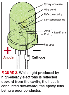
LED diodes consist of a die of semiconductor material impregnated, or doped, with impurities to form a p-n junction (Figure 2). When the LED is switched on – in other words, when a forward bias is applied to the LED – current flows from the anode (“p” side) to the cathode (“n” side). At the junction, higher-energy electrons fill lower-energy “holes” in the atomic structure of the cathode material, due to the voltage difference across the electrodes.
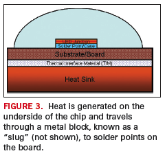
The energy released by the electrons in filling the holes produces both light and heat. The light, in turn, is reflected upward by a cavity created for that purpose, while heat is transferred downward into the base of the LED, and ultimately through a torturous path to where it can be dissipated into the atmosphere by convection, usually with use of a heat sink (Figure 3).
The process of light emission is called electroluminescence, and the color of the light produced is determined by the energy gap of the semiconductor. Since a small change in voltage can cause a large change in the current, care must be taken to ensure both are within spec and are as constant as possible. Otherwise, the performance of the LED can become degraded over time, even to the point of failure.
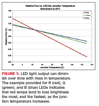
Is heat really a problem with an LED? It definitely can be a problem, and sometimes a difficult one. As the temperature rises within the LED, the forward voltage drops and the current passing through the diode increases exponentially, thereby leading to even higher junction temperatures. (Figure 4 shows how a small change in voltage can cause a significant change in current.) While catastrophic failures probably are rare, an LED module’s light output will diminish over time (Figure 5); efficiency will drop, and the color of the light emitted may change, due to shifts in wavelength brought on by the temperature rise. Wavelengths typically rise from 0.3 to 0.13 nm per °C, depending on the die type. As a result, orange LEDs, for example, may appear to be red, and LEDs producing white light – such as automobile headlights and street lamps – may have a bluish tinge. Other effects include yellowing of the lens, breaking of the wire, and die-bond adhesive damage.
Figure 5 also suggests why white light created from RGB LEDs can appear to have a blue tinge as the junction temperature rises above its intended value. As the figure depicts, blue light falls off slightly less than green and much more so than red.
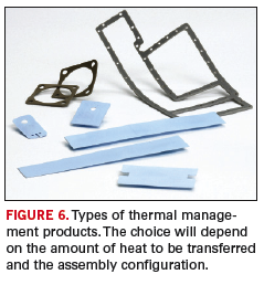
Proper thermal management in designing circuitry and modules containing LEDs is thus essential, and while various approaches are available, involving heat sinks, base plates, constant-current power supplies, and fans, the solution almost always encompasses the selection of materials for attachment, from thermally conductive adhesives to die cut pads, that are electrically isolating and thermally conductive (Figure 6). In most instances, a thermally-conductive/electrically-insulating pad will be the choice in transferring heat to either a heat spreader or a heat sink.
Designing an LED assembly – whether on a circuit board with other components or within an enclosure – first requires an assessment of the methods available for dissipating the heat to be generated by the assembly. Will the LEDs be through-hole or surface-mounted? Should a dielectric substrate be employed with thermal vias and a copper plate on the underside for absorbing and distributing the heat, or will the LEDs be mounted on a coated metal-core board that acts as a heat spreader? In other words, the initial effort is to determine how the heat is to be dissipated and the most efficient and effective heat path for transferring the heat.
Upfront design work for an LED assembly can be performed either in-house by the manufacturer, or with the assistance of an outside service, namely, a converter experienced in the dissipation of heat generated by electronic and optoelectronic components. In some cases, determining how best to dissipate the heat may benefit from in-depth thermal analyses using temperature modeling software for LED-based module designs.
Once the thermal path has been determined, the next step in designing an LED assembly is the selection and configuration of the thermal interface materials. Among these are liquid adhesives, die cut pads, etc. that provide the required thermal conductivity and electrical insulation. Such parameters as surface flatness of the substrate and heat sink, shape and metal used for the heat sink, applied mounting pressure, thickness of the interface, contact area, etc., may also be specified.
Various families of materials have been developed for thermal management in electronic and optoelectronic assemblies. Options include both off-the-shelf or custom formulations in specified thicknesses and configurations, as well as a variety of choices in types of material: conductive adhesives and greases, tapes, ceramic and metal-filled elastomers (also called “gap fillers”), coated fabrics, and phase-change materials.
Adhesives and greases have historically been the means of attaching a heat-generating device to a heat sink, and are relatively inexpensive. Pressure-sensitive tapes are also used for mounting components to heat sinks, as are elastomer gaskets, which can be coated with an adhesive on one or both sides, and can be die-cut into almost any shape. Thermal fabrics are typically fiberglass-reinforced, ceramic-filled polymer sheets that can provide both thermal conductivity and electrical isolation. Tapes, elastomer pads, and coated fabrics can be formulated to achieve specified performance values in terms of dielectric strength, thermal conductivity, and thermal impedance.
Phase-change materials change from a solid to a liquid during the process of absorbing heat at specified temperatures. The net result is the transfer of heat from a heat-generating device, such as a microprocessor, which is thermally coupled through the material to a heat sink.
Note that the role of a converter involves more than recommending the use of certain materials. For most requirements, the converter provides the finished part – for example, a die-cut gasket. Depending on the needs of the manufacturer, the converter should be able to perform the actual assembly work. While the requirement may typically involve thermal transfer, the binder, filler material, size and shape of the pad, type of adhesive, method of application, etc. are electrical insulation considerations. So too is EMI/RFI shielding, if needed. Then, too – again depending on the product – environmental sealing may also be required, since LED applications often entail operation under environmental extremes of temperature and weather, and even vibration. (Consider, for example, the vibration requirements for a sealed LED headlight.)
While LEDs seem cool to the touch, heat can be a significant problem, and could cause a product failure. Though excessive heat is not going to cause a color shift that results in a red stop light changing to green, the traffic signal could go out, or more likely, it could dim to the point of not being easily visible.
In designing LED-based products, the heat generated both by the LEDs and surrounding components, if any, requires serious consideration by the product designer, the materials engineer, and the converter contracted to provide a viable, cost-effective solution.
Chuck Neve is technical sales representative at Fabrico-EIS (fabrico.com); This email address is being protected from spambots. You need JavaScript enabled to view it..
Despite the downturn, several EMS companies found ways to improve workers’ lives both in and outside the plant.
With organizations tightly watching costs and a steady stream of headlines on (high) unemployment rates, it would be easy to assume that companies are no longer willing to invest in their employees. When I surveyed several EMS providers in February, however, I found nothing could be further from the truth. While programs varied, the common link was that all these companies saw investments in improving employee quality of life and skills as a practice that contributed to the bottom line. I selected some program highlights from operations in the US, Mexico, Singapore and Poland to provide a broader look at variations between countries and cultures.
MEC. According to Rick McClain, general manager of MEC NW’s Canby, OR facility, MEC chose to invest in employee development during the downturn by keeping a trainer on staff and enhancing internal capabilities. Training focused on a mix of IPC-A-610 certification training and in-house systems training. One result is that the company recently added IPC-A-610 Class III assembly capability.
There also is a strong focus on continuous improvement (CI). Employees are encouraged to submit CI suggestions that improve one or more of eight identified areas of waste: waiting, rework, overprocessing, transportation, inventory, overproduction, unused employee creativity or motion. At a facility level, MEC has a game similar to the TV show Amazing Race. In this “race,” employees pick a spot on a world map and then earn “miles” based on tracked company improvements. Metrics tracked are revenue, on-time shipments, warranty returns, employee improvements implemented, parts per million (PPM) defect rates and employee fitness (i.e., miles walked, swam or biked). A conversion chart is used to assign miles to each category. If the target mileage is hit, there is a luncheon and prizes that reflect the country originally targeted on the map.
As the metrics example indicates, there is also a wellness program. The company hosts an annual Wellness Fair featuring 10 to 20 vendors and benefits specialists who offer advice on fitness options. Biometric screenings for employees are free, and results are translated to recommendations for a healthier lifestyle. Fitness activities such as walking are encouraged and there is monthly recognition for employees living healthy lifestyles. Fitness club discounts have been negotiated as well.
EPIC Technologies. EPIC Technologies maintains a strong focus on worker training and quality of life in its US and Mexico operations. Here, we focus strictly on its programs in Juarez, Mexico. Mexican law mandates a wide range of employee benefits related to onsite health care, bonuses, vacation and sick leave. EPIC’s programs exceed these minimums. According to Salvador Baca, EPIC’s Mexico human resources manager, good benefits are one way to reduce absenteeism, tardiness and turnover.
Although Mexican law only requires infirmaries be staffed by nurses, EPIC has an onsite doctor too. Nurses are present on all shifts and the doctor during the day. The facility provides prescription medicine and immunizations. Employee families are also treated. According to Baca, the benefit of this extra health care option is improved health for employees and less lost time, since the government’s health care system typically has long waiting times.
The company also has invested in training. A teacher conducts classes within the facility to help employees who haven’t completed high school study for their degree. After six months on the job, employees are eligible for an annual $400 scholarship for special training. In special cases, tuition reimbursement is provided for programs toward a job-related degree. Employees are also sent to schools around the country for special programs related to IPC, ISO/TS-16949, or customer-required training.
While emphasis is on CI initiatives throughout the year, EPIC drives an extra focus on quality once a year with its Race for Quality event. The race adds a competitive element to Lean projects and kaizen events for three consecutive months. Goals are set for projects for each month. If the goals are met, employees get a prize and the best-performing shift gets a double prize. Each monthly goal is more difficult, but prizes are improved as difficulty increases.
Also, focus is on social activities, as Mexico has a very family-centered culture. For example, a special Mother’s Day celebration in May includes mariachis, a special lunch and raffles for all employees who are mothers. Families are invited to an annual picnic in July. A Christmas party for employees in December includes a special dinner and gift for each employee. Sports teams also have been organized. There are internal tournaments for soccer, and the teams also play in a city league with other factories. Basketball and volleyball tournaments are held.
“These types of activities improve the company by encouraging better communications and working environment,” says Baca. “This type of teamwork and communications creates more ownership.” It is not unusual to see companies without such activities experience 25% more turnover than those that invest in expanded benefits, he adds.
Unique at EPIC is its Values Program targeted at employees’ families. Employees who sign up to participate are given monthly homework assignments to take to their children. The assignments are focused on core values such as justice and responsibility. “We want to invest in the community and send strong values messages out to families,” said Baca.
Employees who work with their children in this program are recognized by EPIC with a small gift. At the end of the year, EPIC has a party with the families that participate.
CEI Contract Manufacturing. During the downturn, when asked if layoffs would help create better shareholder value, CEI contract manufacturing managing director Ka Huat Tan replied, “Do you want to create shareholder value for the next three months or the next 10 years?” Not only did the Singapore-based EMS company have no layoffs, it continued to pay small bonuses.
“When times are hard, people become uncertain and edgy,” Tan said. “It is important to make sure people feel valued. CEI is very sensitive to that. We had our HR department informally communicate that there would be no layoffs. During the worst of the downturn, we kept our staff busy with additional training, funded in part through Singapore Economic Development Board incentives. We also bought a new factory with gross space of 40,000 sq. ft. and continued to invest in new technology, which signaled employees we were committed to long-term growth.”
That decision also had positive impact on the bottom line. In 2009, the company received nearly S$600,000 in job credit incentives because it maintained its employment levels.
Tan believes people are a company’s most important asset, but cautions that simply stating that is meaningless if not backed by actions. For example, Tan asked his managers to watch for employees who might be experiencing financial difficulties. While the company didn’t provide cash in those cases, it did provide informal assistance, including suggestions on contacts or resources that could help. “The goal wasn’t to give employees in financial trouble a handout, but instead create a supportive environment that made it easier for them to fix the issues themselves,” said Tan.
CEI has a Work Life Balance committee that consists of a safety committee, a sports committee, a special interest group committee and an HR committee. The company’s Wellness Program is quite comprehensive. HR organizes a 1.5 to 2 hr. quarterly seminar that focuses on health-related topics such as stress management.
Sports teams have been organized for bowling, table tennis and badminton. The company also holds a Sports Day at a local stadium and gets almost 100% employee attendance at the event. There is a recreation room in the facility used for table tennis and yoga classes. A gym with a treadmill, cross trainers and a fitness instructor were recently added.
CEI funded 80% of a 2009 medical checkup to encourage all staff to have diagnostic testing. This testing program provides them with a measure of the general health of the company’s employees that can be compared to Singapore averages. “The statistics show there is room for improvement. Part of showing you care about employees is identifying areas for personal improvement and encouraging them to improve. By studying overall health trends and tracking sick leave, we can tell who abuses sick leave and who truly has health issues that need to be accommodated,” said Tan.
At the last dinner dance, the organizing committee invited staff members who have been exercising to talk about what they’ve learned in the process. Participation in extracurricular wellness activities is part of the equation in determining the size of an employee’s bonus. But CEI’s program also has punitive measures. A pattern of sick leave abuse can impact annual bonuses.
Tan sums it up simply: “We try to encourage the best in our employees, but also have checks and balances to address issues such as sick leave abuse.” Kimball Electronics Group. Kimball has strong programs for sharing corporate values and incenting individual employee development. According to Julie Dutchess, Kimball Electronics Group’s global HR director, the company has been administering Vision and Guiding Principles Surveys in its Poznan, Poland, facility since 2004. In 2007, the Poland group included an additional step in the survey process to provide group and production unit leaders with 360° feedback on softer management skills. Employees’ comments for improvement in previous guiding principle surveys were used as criteria in the feedback process.
“Polish culture always placed high value on work ethic and accomplishing goals, and when they added focus on the softer interpersonal relationship management skills, they could see the positive impact,” Dutchess said. “The survey allows us to measure how supervisors and managers are improving in terms of the way they manage. Tracking rating trends the same way we track metrics for on-time delivery or quality has helped the staff to realize the importance of this area of management skills, and we have seen visible improvement over time.”
Another area of improvement has been in worker skills. Originally, employees’ jobs were focused fairly narrowly. As the company’s customer base has grown in size and diversity, so has the need for greater flexibility on the floor. Keeping headcount the same meant training operators for several job stations.
“Originally people didn’t like this. They were used to doing the same job. We told them that if they were willing to develop themselves and gain new knowledge through training, their promotion ability and earning potential would grow. Some embrace this; others do not,” said Magdalena Okon, the Poland facility’s HR manager.
The new program created a core group of employees called multi-operators. When demand varies, Kimball can very quickly shift employees between production lines. To qualify as a multi-operator, the operator must be trained and certified for 60% of the job stations within the production area.
Multi-operators are paid more and are prioritized for promotion to higher levels, such as group leader or transfer to other departments. Okon points out that this has helped to create a clear path for career advancement on the production floor. Currently 80% of internal promotions come from the pool of production operators. One other path for career advancement is Kimball’s Individual Development Program. “People development is everyone’s responsibility. HR supports by providing engagement, tools and knowledge. Participants must have a vision for their career. Kimball can help, but the employee is the owner of their own development,” said Okon.
IDP has several goals:
Development and retention of key employees.
Assurance of successors for key management positions in the organization.
Improved employees’ satisfaction as the result of advancement potential.
A class of candidates are selected every two years. Candidates must fill out an application that outlines long-term career aspirations and a plan to achieve them. There is a a follow-up interview with HR and their immediate supervisor. Managers in each department then nominate the employees they feel have the most development potential.
An IDP Council composed of the managers of the facility, quality, production, HR and an HR specialist reviews the nominees and chooses final participants. It is interesting to note the selection process looks at organizational resources in terms of availability of mentors and the availability of career path advancement, in addition to the relative merit of each candidate. No more than seven candidates are selected per IDP class.
Once selected, the candidate, HR and the candidate’s immediate supervisor identify the key skills that need to be developed to perform well in the final position and create a detailed plan that lists skills, development activities, responsibilities, timeline, risks, cost and status of execution. External consultants verify the level of competencies while the candidate is in development. Every six months, HR checks plan status and collects feedback from participants. The information also is discussed with the IDP Council.
“Not everyone stays,” Okon said. “In some cases, there is no path for further progression, and a candidate opts to leave the program to pursue other opportunities. We do debrief candidates who leave to determine what went well and what could be done better. It is definitely worth the risk of investing in training. In the end, even when we lose someone because the organization is not ready to utilize his or her full potential because a desired advancement opportunity isn’t available, we still have the opportunity to get some benefit from his or her talent while the candidate is growing. We would probably lose the candidate much sooner if we did no development. The program has helped fill some key slots.”
One key measure of the success of Kimball’s program is turnover. According to Okon, while voluntary turnover in the Poznan region averages 8% per year, Kimball’s Poland facility’s annual turnover rate is 2%.
Each of these companies has taken basic good management practices and used them creatively to increase motivation and productivity, reduce turnover and improve employee quality of life. Given that employees are often the key differentiators between one EMS provider and another, it appears money well spent.
Susan Mucha is president of Powell-Mucha Consulting Inc. (This email address is being protected from spambots. You need JavaScript enabled to view it.), a consulting firm providing strategic planning, training and market positioning support to EMS companies. Her book, Find It. Book It. Grow It. A Robust Process for Account Acquisition in Electronics Manufacturing Services, is available through barnesandnoble.com, amazon.com and the IPC and SMTA bookstores. Her column runs bimonthly.