High-Speed Constraint Values and PCB Layout Methods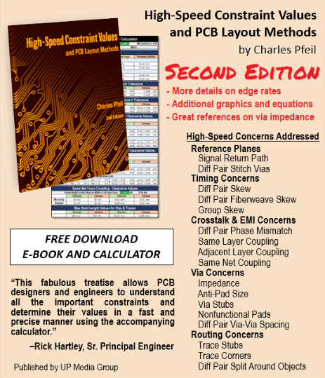
by Charles Pfeil (Forward by Rick Hartley)
How to Receive Your Copy
To download your free copy of this new e-book and the Constraint Value Calculator today, please submit your name and a valid email address. Be sure to click the Request Download Link button. A link to the downloads will be emailed to the address provided.
If you enter a name and valid email address and do not receive the link, try flushing your cache. This can be accomplished by pressing CTRL+F5. Then return to this page and re-enter your name and email address.
About the Book
High-Speed Constraint Values and PCB Layout Methods encompasses lessons learned from Charles Pfeil’s five decades in PCB design. It covers critical length, reference planes, timing, skew, crosstalk, coupling, vias, and routing. The book provides the underlying equations and specializes in practical solutions for real-life signal problems.
Constraint Value Calculator
This download includes the Constraint Value Calculator.
The Constraint Value Calculator is an Excel-based worksheet developed by Charles Pfeil. The faster the edge rate, the more likely the signal will have timing, crosstalk and signal integrity problems. Also, the constraint values become tighter as the edge rate increases. As such, the Constraint Value Calculator provides rules with appropriate constraint values for high-speed designs. It includes options for edge rate, dielectric constant, and height between the layers to determine constraint values.
About the Author
Charles Pfeil has spent over 50 years in the PCB industry as a designer, owner of a service bureau, and in engineering management and product definition roles at Racal-Redac, ASI, Cadence, PADS, VeriBest, Mentor Graphics, and Altium.
Most of his career was at Mentor Graphics, where he was a software architect focused on advanced development of PCB design tools. He was the original product architect of Expedition PCB, and an inventor of Team PCB, XtremePCB, XtremeAR, and the Sketch Router. He previously authored BGA Breakouts and Routing.
He was inducted into The Dieter Bergman Hall of Fame for PCB Design in 2013.
-
Details
-
Written by Adam Ley
Over the last few decades, in-circuit test (ICT) has been integral to the growth of the electronics industry. Now though, because of rapidly accelerating speeds and new levels of complexity, chips, circuit boards and systems are moving beyond the reach of the intrusive probes and bedof-nails fixtures that ICT depends on. This white paper explains the technical and economic factors that are contributing to the gradual but inevitable demise of ICT and how non-intrusive board test (NBT) has emerged as a more cost-effective and thorough test technology for the manufacturing floor. Certainly ICT will continue to have its place, albeit current trends indicate it will soon be relegated to special case testing or for testing rudimentary circuit board designs. Simply stated, electronics manufacturers (original equipment manufacturers or original design manufacturers) are finding it increasingly difficult to make a credible business case for ICT, especially when NBT offers better test coverage and a lower cost structure.
http://www.asset-intertech.com/Media/en-US/Documents/Whitepapers/Solving_the_problem_of_diminishing_test_coverage_from_ICT.pdf
-
Details
-
Written by Philips Lumileds Lighting Company
When designing LED-based lighting systems, engineers need to understand LED lumen maintenance and mortality in similar terms to those used when designing with conventional light sources. However, comparable data has been nearly impossible to find. In addition, designers need extra information to predict the lifetime of LEDs under a variety of operating conditions. A number of techniques to predict LED lifetimes have been proposed, but these have not been sufficient to generate the clear and unambiguous data that lighting engineers can use easily. This white paper provides lighting designers with an understanding of a new tool introduced by Philips Lumileds Lighting that simplifies the process, allowing flexibility in design options. This one tool provides designers with information that they need to make decisions about product lifetimes, driver constraints, number of LEDs required, and thermal management.
Link here