A mismatch in trace symmetry can cause noise coupling or timing issues.
So, what exactly are differential impedance traces, and how do they work?
I remember a story from a former colleague about how their engineering team had spent nearly a month trying to solve a mysterious bit error rate (BER) issue on a seemingly well-designed and otherwise sound PCB. After many painstaking diagnostic hours, not to mention added resources and a looming release date, they finally found their answer. What was it? I’ll get back to that.
With the ever-growing requirement for more densely populated PCBs, paired with the added complexity of high-speed signals in modern electronics, mitigating the effects of electromagnetic interference, noise, and crosstalk is crucial for proper circuit functionality. One commonly implemented design technique is the use of differential signals. To better understand the concept of differential signals, let’s first look at how single-ended traces behave.
A single-ended trace is, well, just that: a single trace with one starting point, one ending point, and a common ground, carrying a signal from a source to a receiver. When you start packing more traces at higher speeds on the same board, the potential for noise coupling on sensitive traces gets greater.
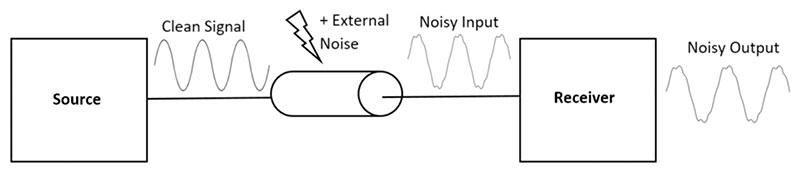
Figure 1. Rendering of a single-ended trace, with noise effects.
Noise from EMI can change digital logic levels to unrecognizable values, leading to potentially critical issues on data lines. Alternatively, when using differential signals, the receiving input measures the difference between two signals – one positive and one negative – instead of the difference between one signal and a reference voltage. By designing the two traces with nearly identical symmetry, and then placing them very close together, EMI and other unwanted noise should be coupled equally on each trace. Because the same noise is present on both traces, when the difference is taken between the signals, the noise gets canceled out. Thus, the output signal will remain consistent regardless of the presence of unwanted common mode noise.
Differential pairs sound great. What could go wrong? In the design of differential impedance traces, very close attention to length, impedance, spacing and via count/positions of the pairs is imperative for proper functionality. A mismatch in symmetry on the traces can mean unequal noise coupling or a time delay between each signal reaching the receiver, resulting in an inaccurate output signal.
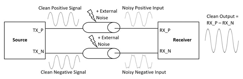
Figure 2. Two traces with nearly identical symmetry, placed close together, can cancel out noise.
This leads me back to the story of my former colleagues. Their BER problem was ultimately caused by a timing discrepancy on a pair of high-speed differential traces. To put it simply, the length of one trace was too long in relation to the other. This resulted in one signal arriving at the receiver before the other, and, subsequently, an inaccurate “difference” between them. Once the trace lengths were properly redesigned, the BER dramatically improved, which then resulted in a successful product launch, albeit a little later than promised and a with few more gray hairs sprouting on the heads of the team members.
These types of signal integrity issues can be incredibly difficult and expensive to retroactively diagnose, not to mention stressful. The best solution is to find them on the front end. Some CAD tools can automatically check for consistency in the length, spacing and via count/positions of differential pairs. By taking a couple minutes to run this rule on your design, it is easy to recognize a potential symmetry flaw in differential traces before the PCB is sent to the manufacturer.
Rebecca Lord is technical marketing engineer at Mentor (mentor.com). She has a bachelor’s in computer engineering and was previously a hardware engineer in the data storage industry.


