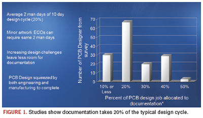
Dedicated tools help reduce the once-manual job by 20% of the typical design cycle time.
The question posted to the DesignerCouncil email forum was simple and straightforward: “Why on earth can’t these companies make a product out of the box that does engineering documentation well? I find it hard to believe there can’t be a boilerplate level delivered that could handle 80 to 90% of most companies’ documentation needs out of the box. … Even the BoM reports delivered out of the box from Oracle are absolutely useless. You need an integration company or an internal team of Oracle experts to spend a fair amount of effort just to get a usable BoM report.”
What’s fascinating, if not somewhat predictable, is how many firms take software that is intended (and good) at one function and repurpose it for something else. Take, for example, two of the best-known product life management tools: Oracle’s PLM and PTC’s Windchill. Good programs, both, but they were never intended to handle circuit board documentation. It’s one reason why it takes, on average, two man-days of the typical 10-day design cycle to complete the documentation (Figure 1).
Best-in-class processes reduce the amount of time spent creating the documentation; are automated so as to create a “living” document, or one that’s not fixed in time, unlike a paper printout of a pdf where, in the event of an engineering change order, the documentation needs to be regenerated; and facilitates product flow to the extent that the end-product quality is enhanced. As Downstream Technologies cofounder Joe Clark says, “Documentation is much bigger than just design, fab and assembly.”
Designers are pros at stretching the limits of CAD tools and other software, but at some point the deficiencies become too glaring to tolerate.
It’s why I’m surprised more haven’t turned to BluePrint, which purports to solve the headaches by providing access to all the electrical intelligence contained in the PCB CAD database to create detailed documentation in reportedly a far shorter timeframe than using traditional ECAD or MCAD tools.
The brainchild of DownStream, BluePrint was developed by former board designers who understand from firsthand experience the pains of their ex-colleagues. It uses a drawing- and sheet-based approach to create actual PCB documents (drill drawing, assembly drawing, parts list, and so on), and stores them in a digital release file. BluePrint uses the CAD data to automatically create unlimited views, details, and charts of the PCB, and can revise the documentation to reflect new PCB changes, reportedly in seconds. It’s not just a tool change; it’s a change in methodology.
Like MCAD, BluePrint can document drafting and dimensional specifications. Where BluePrint separates itself from the traditional MCAD tools, however, is in the
number of required translations. Mechanical tools aren’t designed for the specific nature of a printed circuit board. To wit: MCAD cannot distinguish between a layer on a circuit board and a floor of a building. Meanwhile, BluePrint is a full 2-D drafting tool designed specifically to create PCB documentation and capable of creating anything that the CAD, fabrication and assembly departments might need. It eliminates constraints imposed by the PCB design tool for documentation, but retains the intelligence lost when using an MCAD tool for documentation.
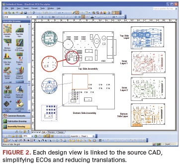
The best example of this is BluePrint’s support of unlimited PCB design views on any drawing sheet. Each instance of the design can be set with different display settings, scaling and formatting. However, each is also linked to the source CAD to automate ECOs, requiring one file translation from the source PCB CAD data to BluePrint (Figure 2).
As our emailer suggested, most users try to generate documentation from their ECAD tool. But ECAD was never intended for that purpose: Dimensioning is the domain of mechanical design. In practice, it’s another story. Asserts Clark, “Users do [documentation] in ECAD because they need to get it onto the piece of paper. There are lots of things done in the electrical design process that have nothing to do with electrical design; it’s all aimed at the documentation.” For instance, the use of assembly variants or mechanical components, which are never simulated but are pushed into a design capture or PCB layout tool to ensure they are represented in the final bill of materials.
BluePrint was developed to work with existing EDA tools. The MS Office environment requires a single load of the entire PCB CAD database to start the documentation process, and uses all the CAD intelligence to help create the documentation. ECOs are added by “refreshing” the source CAD data. BluePrint refreshes the documentation package, adding the new data in every instance of a board view, detail and chart.
“BluePrint brings ECAD design into the documentation tool,” says Clark. There, in the gallery (also known as the library, the term “gallery” is used so as not to be confused with the data for the PCB packages and land patterns), users create a drawing sheet, dragging and dropping the elements onto it. Any element – the number of zones, the font, colors, format, and so on – that is dragged and dropped on a sheet is “intelligent”; links remain active from the underlying design database, so if the links change, everything within the drawing is updated.
Inside the file are contained via stackup and drill layer pairs; drill symbols, patterns and charts; notes and callouts; mechanical component support; parts lists and assembly drawings; tooling, and so on. Schematic, Gerber, DFX, PDFs, plus any graphic or audio files are all stored. Or, in the words of Rick Almeida, DownStream’s cofounder, president and a former designer, “Any data used to create documentation and drive manufacturing.”
Automation of documentation is created by first creating the graphical “pictorial” of how the user wants to see a specific documentation element, for example, a “Via Stack-Up.” The graphical instruction defines how the via stackup should look. The via stackup could be amended, and the template modified to company-specific versions and saved for reuse. The template graphics are linked to data fields that pull the correct information from the PCB CAD data to intelligently create a via stackup that reflects the design intent and remains linked to the CAD data, so when the CAD data are updated (e.g., new layers or via ranges added or deleted) the detail is also automatically updated. “Essentially we use the same approach that is found in MS Excel chart build, where empirical data are married to user-specific graphics,” says Almeida. This same process goes for drill charts, parts lists, finger chamfers, coordinate lists, exploded views, etc.
BluePrint supports automation of the assembly drawing as well. This includes parts lists, which, even if not shown in the documentation set, are in the underlying design database and can be referenced as needed. The search function can find specific parts and component outlines. What it is not is a bill of materials management tool. “The parts list is a key part of the documentation,” explains Clark. “Documentation affects the parts lists, because as designers do the layout, they add mechanical parts, such as face plates, screws, washers. They need to be able to add to the parts lists and export them to the right department so they can add to the BoM and bring in all the attributes of the parts.” With BluePrint, users can import an external parts list from PLM or other enterprise systems, and sync the parts list with the assembly document, then export the parts list back to the enterprise system for ongoing management.
BluePrint follows the orientation of the board to place component reference designators. (The latter can be hyperlinked, too.) Assembly variants can be created at both the parts list level and also with a graphical assembly pictorial, with special legends to show what’s been installed, uninstalled or substituted. Documents such as relevant standards can be inserted as hyperlinks into the database. It also can generate rework sheets, showing cuts and jumpers, and include installation procedures.
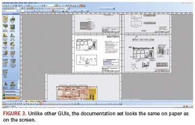
One complaint about reference designators in Oracle and SAP is that they do not display all instances of a particular part number with the part number and description in a single screen or menu. That’s not an issue for BluePrint. The documentation set in the GUI looks just as it will print on paper (Figure 3). The documentation package also can be exported as a pdf and posted to the Web, or as html on a company Intranet.
“It treats the end-product like a PCB, not a generic widget,” Clark says. “We don’t know how good our documentation is until we print it. Then, if something is wrong, we need to go back upstream and fix the ECAD database, then print again. What we do is allow the user to work with the documentation as it will be delivered upon release. This is a full 2-D drafting tool; it’s not intended to replace the mechanical group, but you need to be able to move and place things when doing the documentation. The handcuffs need to be removed.”
As we reported several months ago, Qualcomm has become one of the largest companies yet to standardize on BluePrint. Come this time next year, I would expect many more such announcements – and far fewer plaintive missives like the one at the beginning of this story.
Mike Buetow is editor in chief of PCD&F/CIRCUITS ASSEMBLY; This email address is being protected from spambots. You need JavaScript enabled to view it..


