 At the highest magnifications, the differences between the two types of targets become clear.
In these columns, I have often mentioned the term geometric magnification (GM) and how this value defines the available magnification for x-ray imaging. GM is the ratio of the distance between the x-ray source and the detector and the distance between the x-ray source and the sample. Therefore, the closer the x-ray source can get to the sample for a fixed detector distance, the greater the available imaging magnification. However, these GM distance measurements are defined from the point of origin of the x-rays within the x-ray tube, called the focal spot, and not the point from which the x-rays physically exit the tube housing. This distinction is important to understand, as the configuration of the x-ray tube in a particular x-ray system will have an in-built separation distance between the location of the focal spot and the point of exit of the x-rays through what is called the tube x-ray window. Depending on the x-ray tube used, this in-built separation distance may be a much greater limiting factor to the available image magnification that an x-ray system can provide compared to how close the x-ray window can be placed relative to the sample. As such, x-ray tube choice may impact the capability of an x-ray system to see to a magnification adequate to permit sufficient analytical quality of the smaller, and continually shrinking, features within electronics boards and components.
To understand why this is the case, it is necessary to appreciate how x-rays are produced within the tube. In simple terms, the x-ray tube generates electrons that are then accelerated toward a metal target through an applied voltage. The high energy impact of the electrons on the metal produces the x-rays. During x-ray tube operation, the accelerating voltage is known as the “kV.” In principle, any metal could generate x-rays, but for electronic applications tungsten (W) is most common. Operationally, all this takes place within an evacuated environment to ensure the electrons can travel toward the target without being stopped by intervening air molecules and potentially damaging the electron-generating component. Once the x-rays have been created, they need to exit the tube housing. This is where the type of x-ray tube target impacts the available magnification. X-ray targets can either be transmissive or reflective in their style (FIGURE 1).
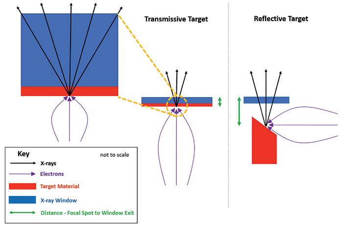
Figure 1. Schematic of transmissive and reflective target type x-ray tubes indicating the substantial difference in the distance of their focal spots to the exit of their x-ray windows.
Transmissive targets have a very thin layer of target material (< 10µm thick) directly bonded to the x-ray window (typically around 500µm or 0.5mm thick). The window material could be diamond, beryllium or aluminium. Diamond and beryllium are transparent to x-rays, hence the term window. Aluminium is not transparent to x-rays, but as it is a light element and the thickness used is small, its effect on x-rays passing through is relatively minimal for electronics applications. Once the incoming electrons hit the front side of the target material, x-rays are produced and transmit through the target material thickness into the window material before exiting the tube, hence the transmissive name. Some self-absorption of the produced x-rays does occur as they pass through the target material, and that is why the target material is so thin. Typical total target plus window thickness is 0.5mm or less. Therefore, this is physically the closest a sample can be placed to the focal spot. In contrast, reflective targets, as their name suggests, have the produced x-rays reflecting off the front surface of the target before exiting the tube through the window. As the x-rays do not need to pass through the target, the target material can be of any thickness. A typical minimum distance from focal spot to window exit for a reflective target x-ray tube is ~8mm, which is 16x the distance of the typical transmissive target x-ray tube described above.
Different x-ray tubes from various manufacturers will vary slightly from these values, of course, but based on these numbers, what does this mean for the geometric magnification of an x-ray system where the detector is 300mm from the focal spot of both tube types? For a very thin sample placed outside on the window, the transmissive tube would give a maximum available GM of 300/0.5 = 600x. The reflective tube would give a maximum available magnification of 300/8 = 37.5x. If we then consider a more real world application where a BGA sits atop a 2mm thick board, in these respective system configurations the transmissive tube provides maximum magnification of 300/(0.5 + 2) = 120x, and the reflective tube gives 300/(8 + 2) = 30x. In both situations, the maximum available magnification will continue to reduce as the sample moves farther away from the tube.
What does this difference in available magnification mean in imaging terms? As an example, FIGURE 2 shows a low-magnification image of QFNs on a test board. In this image, the sample is substantially farther from the tube compared with any in-built focal spot to window exit distance. Therefore, in magnification terms, x-ray tubes with either target type are acceptable to provide a suitable image for analysis. The differences between transmissive and reflective targets become more apparent at the highest available magnifications (FIGURES 3 and 4). Figure 3 shows an x-ray image of a section of the same sample where the focal spot to sample distance is 8mm, as for a reflective target. Figure 4 has the focal spot to sample distance set at ~ 0.5mm, as for the transmissive target. The difference in available analytical detail between the two images is clear. As samples become thinner and contain smaller features, the difference in what can be seen in the images available at maximum magnification becomes greater.
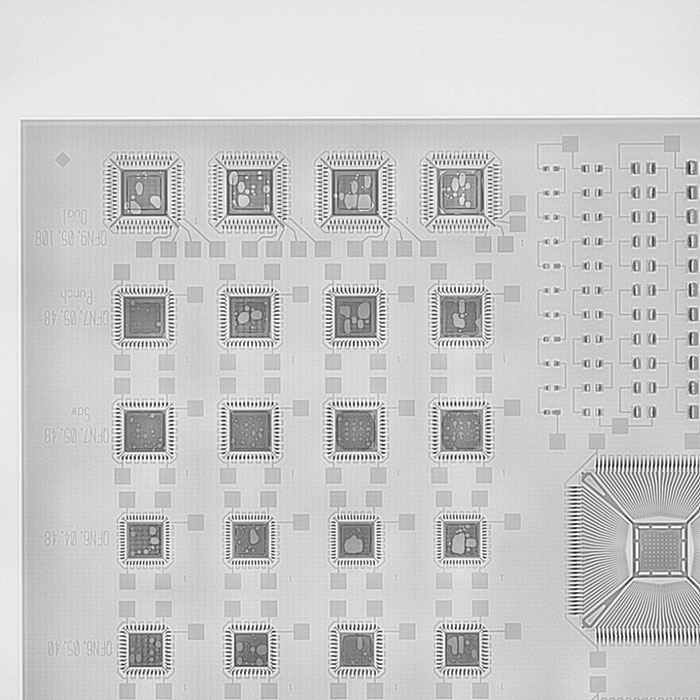
Figure 2. Low-magnification x-ray image example, achievable with x-ray tubes containing either a transmissive or reflective target.
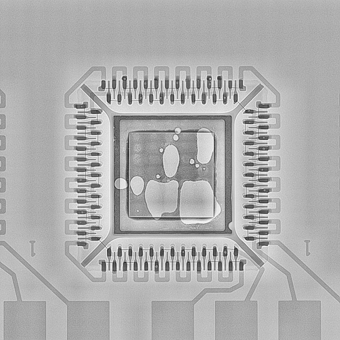
Figure 3. X-ray image showing the maximum available magnification for the same sample placed ~10mm from the tube focal spot, representing a reflective target x-ray tube.
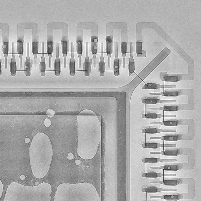
Figure 4. X-ray image showing the maximum available magnification for the same sample placed ~0.5mm from the tube focal spot, representing a transmissive target x-ray tube.
In this column I have concentrated on the impact to image magnification caused by transmissive and reflective targets. There are other issues/differences these target types have in relation to image quality caused by x-ray focus (resolution) and power; these will be discussed in a future column. For now, when considering a new x-ray system, ensure there is sufficient available magnification to see the features you must inspect, both now and for tomorrow’s applications.
Au.: Images courtesy Peter Koch, Yxlon International.
David Bernard, Ph.D., is an expert in use and analysis of 2D and 3D (CT) x-ray inspection techniques for electronics; This email address is being protected from spambots. You need JavaScript enabled to view it..


