
Flex boards are as much mechanical as electrical, so the shape must be right.
Question: I need a flex circuit for my device, but I have never designed one before. (I have done rigid PCBs.) Where do I start, and what is the process for designing a flexible circuit?
Answer: This might have to be a two-parter to cover everything in sufficient detail. While every application is different, a number of typical steps are involved in the flex circuit design process.
Paper doll. Usually the first step is to lay out the circuit how it will look when flat. In some applications this is quick and easy, but in others where the circuit will be formed in three axes, it can be much more time-consuming. A flex circuit is as much a mechanical device as it is an electrical device. The shape of the circuit will be the first determinant of how the final flex circuit will perform mechanically, so it is important that this is done right.
I like to start by laying out a rough first pass on CAD, and then printing the shape on paper and cutting it out (like a paper doll). Then, I try to install the paper doll where the flex circuit will eventually reside. There undoubtedly will be several areas where the paper does not fit precisely. Make the required modifications to the CAD file; create a new paper doll, and again try to install it. This procedure needs to be repeated until the paper doll fits nicely into the area where it needs to be.
Now it is time to take a critical look at the circuit shape. In almost every application, multiple circuit shapes can make all the required connections. Some make good use of the processing panel, and others do not (Figure 1). But since you will be buying the entire panel from the flex circuit manufacturer, you want every square inch of usable real estate to have circuitry on it. In reality, perfect panel usage doesn’t happen very often, but the more efficient the circuit shape is, the less the final product will cost. Another thing to watch for when installing the paper doll is how easy it was to get it into place. Did the paper tear while trying to get a troublesome protrusion into the spot it needed to be? If so, you may have created an assembly nightmare that will cause operators on the floor to curse your name every time they pick up one of your flex circuits. While efficient panel usage is important, ease of assembly is usually trump. If the circuit is difficult to install, it will take the operators longer and raise the possibility of damage to the circuit during installation.
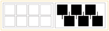
Figure 1. The small extension on each circuit on the bottom panel caused the processing panel density to drop by 25%, which will result in a similar increase in circuit cost.
Now that the shape and ease of installation have been evaluated, either scrap it and try a different shape (if the design looks like a problem child), or move to the next step (if the design installs easily).
Mylar model. Some designers choose to take the paper doll to the next level and create an additional model using polyester (Mylar) film. The nice thing about Mylar is that it will feed through most copy machines. This allows you to print the circuit shape, along with other features such as fold lines, right on the film. So all you have to do is print and cut out with scissors. Mylar will more closely mimic how a flex circuit will behave than paper, so it makes for a good test of the designed circuit shape. Once the Mylar model is completed and functioning to satisfaction, you can move on to the next step.
Mechanical model. Because the circuit outline is such a critical feature to the overall performance and reliability of the flex, many designers choose to order a mechanical mockup from their fabricator as a final check for form and fit. Most flex manufacturers will provide this service for a small fee, or at no charge. A mechanical model will be made up of the exact materials that the flex will be constructed from, except that all conductive layers will be solid copper (i.e., no etching of circuitry). The model will have, however, all the drilled mounting holes and stiffeners of the actual circuit. This will permit connectors and other hardware to be installed to the mechanical mockup with epoxy or glue, and provide a thorough review of the circuit fit and ease of assembly. Many designers over the years have told me that the mechanical mockup saved them because it showed a design flaw that the paper and Mylar models had missed. For the mechanical mockup to provide the most value, it must closely replicate the mechanical properties of the finished flex circuit, so define the number of layers, copper weight, and dielectric thicknesses (if there is impedance control).
I will pick up with conductor routing in the next installment of "Ask the Flexperts."
Mark Finstad is a senior application engineer at Flexible Circuit Technologies (flexiblecircuit.com); This email address is being protected from spambots. You need JavaScript enabled to view it.. He and co-“Flexpert”
Mark Verbrugge from PICA Manufacturing Solutions (This email address is being protected from spambots. You need JavaScript enabled to view it.) welcome your questions.


