High frequency current wants to concentrate near conductor edges. How to compensate for it.
Skin effect is the tendency of high-frequency current to concentrate near the outer edge, or surface, of a conductor, instead of flowing uniformly over the entire cross-sectional area of the conductor. The higher the frequency, the greater the tendency for this effect to occur.
There are three possible reasons we might care about skin effect:
- The resistance of a conductor is inversely proportional to the cross-sectional area of the conductor. If the cross-sectional area decreases, the resistance goes up. The skin effect causes the effective cross-sectional area to decrease. Therefore, the skin effect causes the effective resistance of the conductor to increase.
- The skin effect is a function of frequency. Therefore, the skin effect causes the resistance of a conductor to become a function of frequency (instead of being constant for all frequencies.) This, in turn, impacts the impedance of the conductor. If we are concerned about controlled impedance traces and transmission line considerations, the skin effect causes trace termination techniques to become much more complicated.
- If the skin effect causes the effective cross-sectional area of a trace to decrease and its resistance to increase, then the trace will heat faster and to a higher temperature at higher frequencies for the same level of current.
Faraday’s Law (of magnetic induction) is the fundamental principle behind EMI and crosstalk. It is also the fundamental principle behind a motor or a generator. Simply stated, Faraday’s Law says A changing current in one wire causes a changing magnetic field that induces a current in the opposite direction in an adjacent wire.
But here is the step that is not particularly intuitive. If a changing current in wire A can cause a changing magnetic field, and that changing magnetic field can induce a current in the opposite direction in an adjacent wire B, then that changing magnetic field can also induce a current in the opposite direction in wire A, itself. This is the fundamental nature of inductance.
Consider a wire, A. Assume the current in wire A suddenly increases. At the very first instant of time, there is a changing magnetic field around A that induces a current in the reverse direction in A that cancels out the original current. The net change in current in A is zero. At the very next instant of time, the changing magnetic field around A begins to decay slightly, and a small amount of net current begins to flow. At the very next instant of time, the changing magnetic field decays a little more, and a little more net current begins to flow. This process continues during successive instances of time until the full increment of current is flowing along the wire. This is the nature of inductance and describes the effect of inductance on current flow.
Suppose the process described above is interrupted. Let’s say halfway through, the original current suddenly changes direction. Now the process starts over, but this time in the opposite direction. Every time the original current changes direction, the process starts over in the reverse direction. The number of times the original current changes direction each second is the frequency of the current. If the frequency is high enough, the full current never gets to flow across the entire cross-section of the wire.
Now, during this process, here is the question: During the period of time in which the magnetic field is decaying, where does the current flow? It flows where the magnetic field is weakest. And the magnetic field weakens the further it is away from its source. Its source is along the center of the conductor. So the current that does flow tends to flow strongest the further the distance from the center of the conductor – that is, along the outer surface. This is the skin effect.
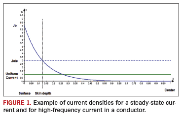
Steady-state currents flow uniformly across the entire cross-sectional area of the conductor. When we think about the skin effect, we tend to think in terms of the current flowing only at the outer surface. This is not really true. The issue really is current density. Normal currents have a current density that is uniform and equal everywhere over the cross-sectional area. But currents impacted by the skin effect have a current density that is highest at the surface of the conductor, decaying exponentially between the surface and the center of the conductor.
If current density is represented by J, then:
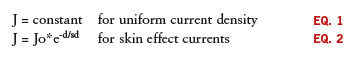
where
Jo = current density at the surface of the conductor
e = base of the natural logarithm (2.718).
d = distance measured from the surface toward the center of the conductor
sd = skin depth
Figure 1 illustrates the two cases of uniform current density, and current density impacted by the skin effect.
Skin depth. Skin depth is defined as the point where the current density is the current density at the surface (Jo) divided by e, or
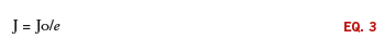
The skin depth defines a cylindrical shell at the circumference of a wire or a rectangular shell around a trace. We tend to think in terms that the current flows uniformly through that shell, and not anywhere else along the conductor. Therefore, the effective cross-sectional area of the conductor is that shell, and the effective resistance the current sees is the resistance defined by that shell. But if current density follows an exponential function from the surface to the center of the conductor, then this can’t be the case. The true effective cross-sectional area only can be determined by using calculus; i.e. integrating the area under the current density curve.
Here is the interesting thing. It can be shown mathematically that multiplying the current density at the surface (Jo) by the cross-sectional area defined by the skin depth will result (at least approximately) in the same answer as if calculus techniques were used. Therefore, using the effective cross-sectional area defined by the skin depth works, even though it does not represent the actual truth.
We say the skin depth defines the effective cross-sectional area of the conductor not because this is true, but because it works!
Skin depth is inversely proportional to the square root of the frequency (in hertz):

Two very important things should be noted here: First, skin depth does not depend on the shape of the conductor. Skin depth is a distance measured in from the surface of the conductor toward the center of the conductor. Second, if skin depth is deeper than the center of the conductor, the current is not limited by the skin effect, and the current is flowing uniformly throughout the entire cross-sectional area of the conductor. Therefore, a thicker conductor is limited by the skin effect at a lower frequency than is a thinner conductor.
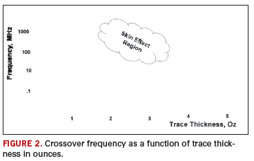
Crossover frequency. Consider a rectangular trace. For simplicity we will consider it to be much wider than it is thick. At low frequencies, the skin depth is deep enough that it extends further than half the trace thickness, and therefore, the skin effect does not come into play. At higher frequencies, the skin depth is smaller than half the thickness, so the effective cross-sectional area is limited by the skin effect. There is a unique frequency where the skin depth is just equal to half the thickness of the trace. This is the frequency where the skin effect just starts to come into play. This frequency is called the crossover frequency.
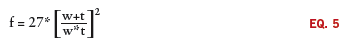
Calculating the crossover frequency can be difficult. For a rectangular trace, I estimate it as:
re
f = crossover frequency
w = trace width
t = trace thickness
A graph of crossover frequency as a function of trace thickness is shown in Figure 2. Skin effect calculations can be difficult. Calculators are available that simplify the calculations by determining several skin effect parameters, including the crossover frequency of a trace, and then frequency adjusted resistance values at user defined frequencies.
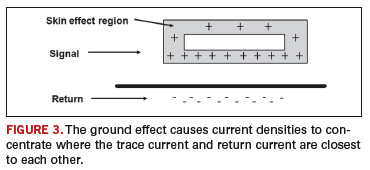
Proximity and ground effects. If frequency is high enough so that the effective cross-sectional area of a conductor is limited by the skin effect, there are two other effects that may also need to be considered. When a signal is close to its return, a mutual inductance exists that may further distort the current flow. Consider a rectangular trace routed directly over and close to a reference plane. If the frequency harmonics are high enough, the skin effect results in the current flowing through an effective cross-sectional area that is a rectangular shell around the edges of the conductor. At the same time, the mutual inductance between the signal current (on the trace) and its return (on the plane) causes the return current to locate itself as close as possible to the signal – i.e., on the plane directly under the trace. This same effect causes the signal current in the rectangular shell to locate more on the planar side of the shell than on the outer side of the shell. This effect is called the “ground effect” (Figure 3).
A similar effect occurs when a signal and its return are on closely spaced wires or traces – as is the case with differential signals. The mutual inductance between the two traces causes the signal currents to distort to the side of the effective cross-sectional area between the two traces. This is termed the “proximity effect.”
Since the proximity and ground effects distort the current path of the signals through the conductors, they further distort the effective cross-sectional area of the conductor, further increasing the effective resistance of the conductor. These effects are very difficult to quantify. Howard Johnson suggests they might be on the order of 30% or so, and he has a good discussion of this on his website.2
Lossy transmission lines. The skin effect, by changing the effective cross-sectional area of a conductor, causes the effective resistance of the conductor to change with frequency. This is of little consequence for most designers most of the time. But there is one circumstance where it becomes very important to PCB designers. The skin effect is one of the two primary causes of losses in lossy transmission lines (the other is dielectric losses.)3
When signals flow down a wire or trace, they reflect back again. The issue is whether we care about this reflection. And we do care if the line is “long” relative to the rise time of the signal.4 The solution to the reflection problem is to design our trace to look like a transmission line and then terminate the line in its characteristic impedance. Figure 4 shows a model of an ideal transmission line and the formula for the characteristic impedance. Of importance is the fact that the characteristic impedance has no phase shift at any frequency, and therefore, it is purely resistive at every frequency.
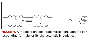
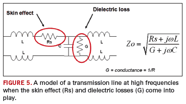
Figure 5, however, shows what happens to a transmission line model at high frequencies when the skin effect (and dielectric losses) come into play. Of particular significance is the fact that there is no single-valued resistor that can properly terminate such a line at every frequency.
The classic symptom of a lossy transmission line is an eye diagram that starts closing. Properly terminating lossy transmission lines is much more complicated than terminating “lossless” lines.5 When frequencies become high enough that the skin effect becomes a factor in traces, the resulting transmission line losses become one of the more significant signal integrity challenges for board and system design engineers.
References
1. Ultracad.com/ucadpcb.htm.
2. Howard Johnson, “Signal Effect Calculations,” sigcon.com/Pubs/news/skineffect.htm.
3. For a good discussion of these two effects, see Howard Johnson and Martin Graham, High-Speed Signal Propagation, Prentice Hall, 2003, pp. 185-216.
4. Douglas Brooks, Signal Integrity Issues and Printed Circuit Board Design, Prentice Hall, 2003, chapter 10, pp. 175-203.
5. Ibid., chapter 17, pp. 311-320.
Douglas Brooks, Ph.D., is president of UltraCAD Design Inc. (ultracad.com); This email address is being protected from spambots. You need JavaScript enabled to view it..


