Elimination of Ni Corrosion in ENIG and ENEPIG by Using Reduction Assisted Immersion Gold
Could a switch from standard immersion gold reduce plating defects?
Ed.: This article is adapted from a paper from the SMTA International Proceedings and is published with permission of the authors.
Nickel corrosion in electroless nickel immersion gold (ENIG) and electroless nickel electroless palladium immersion gold (ENEPIG) is occasionally reported, when encountered at assembly, manifested as soldering failures in ENIG and wire-bond lifting in ENEPIG. Although this is not common, when encountered it is very disruptive. Its presence can cause delays, missed delivery schedules, supply-chain disruption, failure analysis investigations, and manufacturer liability.
To highlight and mitigate nickel corrosion defects, the IPC Plating Processes Subcommittee revised the 2002 standard IPC-4552, Performance Specification for Electroless Nickel/Immersion Gold (ENIG) Plating for Printed Boards. That revision, IPC-4552A, was released in 2017. Work on revision B took place in 2019, and that document awaits a final IPC member vote. Upon release of IPC-4552B, corrosion inspection will become mandatory.
One objective of IPC-4552B is to eliminate nickel corrosion by focusing attention on the defect. Suppliers will have to offer more robust processes, and manufacturers must have tighter process control. One method to eliminate nickel corrosion is reduction assisted immersion gold (RAI). This article addresses the role of RAI gold in eliminating corrosion in ENIG and ENEPIG.
Chemical non-electrolytic gold deposition/plating is the result of a reduction of the gold ion in the solution to the gold metal. Reduction occurs through the supply of electrons. Electrons may be supplied by different methods:
Au+2 + 2e —> Au
- Immersion gold (IG). Displacement reaction where the substrate supplies the electrons needed to reduce the ionic gold to metal. Immersion reaction is limited in deposit thickness capability as the substrate becomes less available. Under non-ideal, IG will corrode the underlying nickel (Ni).
- Autocatalytic gold (AG) deposition. The electrons needed to reduce the gold ions to metal are supplied by a reducing agent component in the bath. This requires an underlayer of IG to initiate. Nonaggressive; will not produce substrate corrosion. Unlimited thickness.
- Reduction assisted immersion gold (RAI) deposition. RAI gold is a mixed reaction bath. Both immersion and autocatalytic reactions start simultaneously (FIGURE 1). As the substrate becomes less accessible, the immersion reaction will diminish, and the autocatalytic reaction will dominate. Non-aggressive; will not produce substrate corrosion. Capable of depositing 4 to 6µin of gold in a single step.
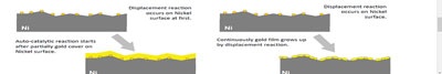
Figure 1. Graphic presentation of immersion gold vs. RAI gold.
Advantages of RAI IG include:
- RAI gold is noncorrosive; eliminates Ni corrosion in ENIG and ENEPIG finishes.
- Economic, one gold bath.
- Capable of depositing higher thickness of gold (up to 7µin), if desired.
This is in contrast with fully autocatalytic (electroless) gold, which requires two gold baths, one for the deposition of an initial immersion gold layer prior to the autocatalytic deposition.
ENIG and RAI Gold
Ni corrosion occurs during IG deposition. It occurs when the Ni deposit is compromised (uneven with deep crevices) in combination with an extended dwell time in an aggressive IG bath (low in Au content, high in acidity). Process control and reduced dwell time in the immersion gold bath are the primary mitigating methods used to date.
FIGURE 2 shows a 5000X SEM micrograph of a corroded Ni surface after gold stripping. An irregular topography with distinct crevices between the domains is where corrosion initiates and may cause black pad.
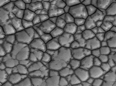
Figure 2. SEM of Ni corrosion.
FIGURE 3 shows a 5000X SEM micrograph of a non-corroded nickel surface after Au stripping. The Ni deposit exhibits an even topography. This Ni deposit will never produce a black pad.
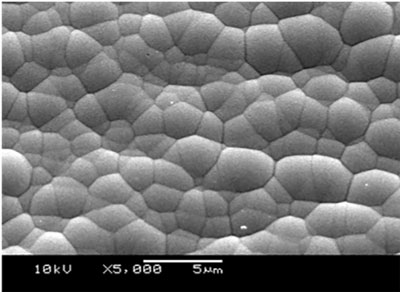
Figure 3. SEM of Ni surface.
A new approach to the elimination of corrosion is the use of RAI IG. The RAI gold mode of action does not rely on the displacement/corrosion step as standard IG does; its autocatalytic deposition mode does not create corrosion. In addition, RAI gold can deposit higher thicknesses of gold (3 to 5µin). Some product designs prefer a thickness exceeding the recommended thickness of 1.6 to 2.8µin. Since Ni corrosion occurs during Au deposition, does the Au bath have a role in causing the defect? Ideally, for every single atom of Ni metal oxidized to Ni ion, two Au atoms are reduced to Au metal. What follows is an investigation of RAI gold as a means to eliminate corrosion in ENIG.
Experimental Design
To demonstrate the capability of the RAI gold bath, sample coupons were prepared and run on two production lines (TABLE 1). The first line utilized a standard immersion gold bath. This sample was used as a reference/control. The control sample was plated in standard gold for 9 min. to a thickness of 2.8µin. All plating was performed using commercially available plating chemicals.
Table 1. Process Sequence and Dwell Time (minutes)
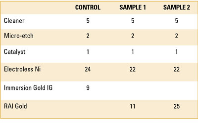
The second line used an RAI gold bath. The coupons in the RAI bath had two distinct dwell times: a dwell time of 11 min. and a dwell time of 25 min. Traditionally, extended dwell time in the Au bath produced corrosion. The extended dwell time addressed two questions: Will corrosion occur, and what thickness of Au can be deposited with RAI gold?
Results and Discussion
Control. The cross-section of the deposit at 1000X, as specified in IPC-4552A and IPC-4552B, shows a low level of corrosion spikes (FIGURE 4). Based on the classification, the spikes are a level 1 or level 2 corrosion, with a product rating of “level 1,” per the proposed IPC-4552B. Although this is not cause for rejection, it is a process indicator that implies higher levels of corrosion are possible.
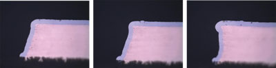
Figure 4. Control sample in standard immersion gold with low level corrosion.
Sample 1. This coupon was plated for 9 min. in the RAI gold to a thickness of 3.2µin. FIGURE 5 shows the cross-sections at 1000X. The cross-section examination showed a product rating level “0” or an ideal deposit with no signs of corrosion that measured 5.48µin. Here the product rating was also at level “0.” TABLE 2 contains values for thickness XRF measurement for Ni and Au.
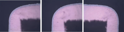
Figure 5. Sample 1 RAI gold at 1000X, showing level “0” corrosion/product rating.
Table 2. Thickness Values for Sample 1
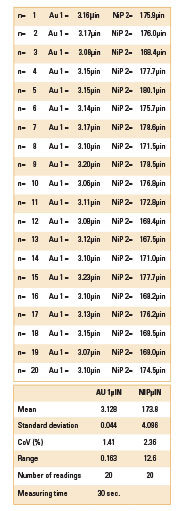
Table 3. XRF Readings for Sample 2
Sample 2. It was decided to test an increased well time in the Au bath. This is the traditional method to produce corrosion. In Sample 2, the dwell time in the RAI gold bath was increased to 25 min. The result was a gold layer with a mean thickness of 5.48µin, with level “0” corrosion (FIGURE 6).
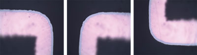
Figure 6. Sample 2 RAI gold at 1000X, showing level “0” corrosion/product ratio.
ENEPIG and RAI Gold
The expectation is that Ni corrosion would not occur in ENEPIG, as the Au ions have no direct access to the Ni. This would be true if the Pd layer is impervious to the Au ions. If the Pd layer is thinner (1 to 4µin/0.025 to 0.1µm), it is not totally impervious, and the Au ions may have access to the underlying Ni, offering an easier path to IG deposition. No corrosion would occur.
The effect of the following attributes in creating nickel corrosion were investigated:
- Thickness of the electroless palladium layer
- Type of immersion gold (standard immersion vs reduction assisted immersion gold).
The test vehicle (FIGURE 7) in this study consisted of a copper-clad laminate substrate Cu-plated to a thickness of 20µm using an acid Cu electroplating process. ENEPIG was deposited on the test vehicle using two different Au baths. The first was a standard IG bath that ran at an acidic pH of ~5.5 at a temperature of 180oF. The second bath was an RAI gold bath, also known as a “mixed reaction” bath. All plating was performed using commercially available plating chemicals.
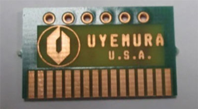
Figure 7. Test vehicle.
The thickness of the Pd deposit was varied by changing the dwell time in the baths. The rate of deposition over time was recorded. The different thickness Pd layers were individually placed in the respective Au baths for an exaggerated dwell time of 30 min. The exaggerated dwell in the Au bath was by design to ensure some level of Ni corrosion would occur, and there would be a way to evaluate the difference the thickness of the Pd layer would play in Ni corrosion and the impact of the type of Au used.
Test #1 involved varying thicknesses of electroless Pd with standard IG. Test #2 involved varying thicknesses of electroless Pd with RAI gold. After each test, cross-sections of the ENEPIG layer at different Pd thicknesses were evaluated for Ni corrosion using SEM.
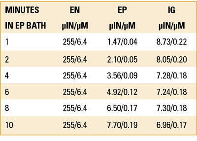
Test #1, ENEPIG with standard IG. Six solder test coupons were plated in electroless nickel at a fixed dwell time and Ni thickness (TABLE 4). This was followed by electroless phos-palladium (EP). The coupons’ dwell time in the EP bath was 1, 2, 4, 6, 8 and 10 min., giving rise to EP thickness that varied from 2-10µin (0.05-0.25µm) of Pd (FIGURE 8). All six samples were then immersed in the IG bath for 30 min. at 180oF.
Table 4. Process Sequence
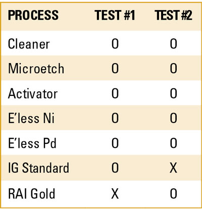
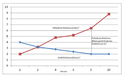
Figure 8. A graphic presentation of the data from Table 2.
Holes from each coupon were then cross-sectioned. Using SEM, 20 corners were evaluated for Ni corrosion at 5000X and 1000X.
The data show Au thickness at the lower EP thickness was as high as 4.0µin (0.1µm) and continued to diminish as the thickness of the EP increased (TABLE 5). Au thickness was limited to 2µin (0.05µm) when the thickness of the EP was 8µin (0.20µm) or greater. The explanation is the Au ions at the lower EP thickness had access to the underlying Ni and proceeded to deposit at an accelerated rate, producing Ni corrosion (FIGURES 9 to 11).
Table 5. Thickness at Different Dwell Times and Corresponding Thickness with Standard IG
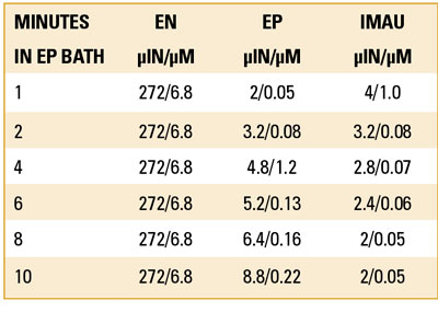
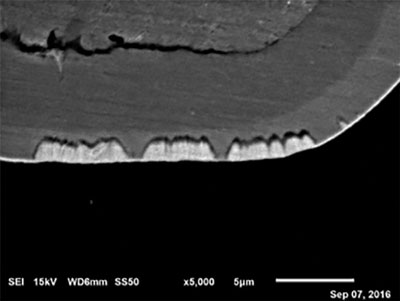
Figure 9. Ni corrosion at 2µin (0.05µm) of EP.
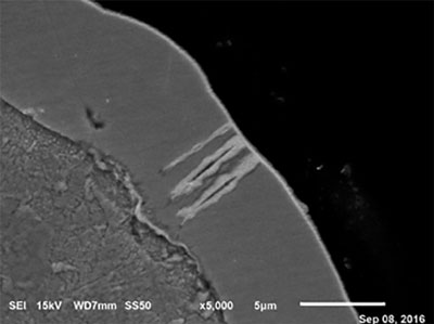
Figure 10. Ni corrosion at 4.8 µin (0.12µm) of EP.
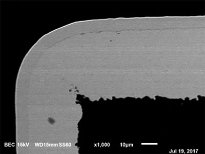
Figure 11. No corrosion at 8.8µin (0.22µm) of EP.
Test # 2, ENEPIG with RAI gold. Test #2 followed the process sequence outlined in Table 4. Six solder test coupons were plated in electroless nickel to fixed dwell time Ni thickness. This was followed by electroless palladium. The coupons’ dwell time in the EP bath was 1, 2, 4, 6, 8 and 10 min., giving rise to EP thickness that varied from 2 to 10µin (0.05 to 0.25µm) of palladium (TABLE 6). All six samples were then immersed in RAI gold bath for 30 min.
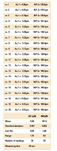
Table 6. Pd Thickness at Different Dwell Times and Corresponding Thickness with Reduction Assisted IG
Holes from each coupon were then cross-sectioned. Using SEM, 20 corners were evaluated for Ni corrosion at 5000X and 1000X. No corrosion was visible with the RAI gold between 2.0µin to 5.4µin (0.05µm to 0.14µm) (FIGURES 12 to 15).
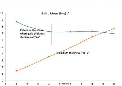
Figure 12. Chart of electroless palladium with RAI immersion gold vs. time in the EP bath.
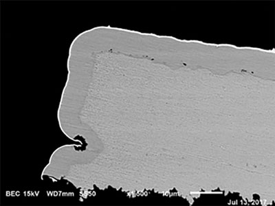
Figure 13. No corrosion at 2.0µin (0.04µm) of palladium.
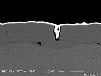
Figure 14. No corrosion at 3.4µin (0.04µm) of palladium.
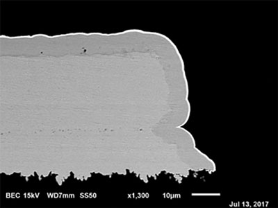
Figure 15. No corrosion at 5.4µin (0.04µm) of palladium.
Conclusions
The results show a major advantage to using RAI gold compared with IG. IG showed major corrosion on the Ni layer, particularly at the lower thickness of the electroless Pd layer. The IG accessed the underlying Ni, creating corrosion. One way to minimize corrosion is to increase the thickness of the Pd layer. Presently, IPC-4556, Specification for Electroless Nickel/Electroless Palladium/Immersion Gold (ENEPIG) Plating for Printed Circuit Boards, specifies 2 to 12µin (0.05 to 0.3µm) for the EP layer and 1.2 to 2.0µin (0.03 to 0.05µm for IG. The authors of this paper recommend increasing the lower limit of EP thickness to 7µin (0.18µm).
On the other hand, the RAI gold did not corrode the underlying Ni, even at very low electroless Pd thicknesses (1 to 2µin).
The data also show there is a limit to how much Au can be deposited using IG (<2.0µin). In contrast, Au thicknesses of up to 8µin were easily achieved with RAI gold.
The results show substituting RAI gold for IG will not corrode the underlying Ni and permit a thicker Au deposit (up to 8µin) on the Pd substrate.
are with Uyemura (uyemura.com); This email address is being protected from spambots. You need JavaScript enabled to view it.. Milad is co-chair of the IPC Plating Processes Subcommittee.


