The Paperless Factory
The Digital Product Model of IPC-2581 is making assembly operations paper-free.
As a founding member of the IPC-2581 Consortium, the growing interest in the IPC-2581 format is exciting. Even more exciting is to see this intelligent format in use throughout the industry today. IPC-2581 has gained momentum from CAD, CAM, fabricators, assemblers and OEMs. Many companies are working together toward the common goal of ensuring this open format is not only widely adopted but is also leveraged to the fullest by all segments of the PCB industry.
IPC-2581 is not just another format. It is an open, intelligent data format that is complete enough to ensure its longevity. What is notably different about the IPC-2581 format from its predecessors? This is the first time in my career I have witnessed so many companies work together to develop a data format that takes every step of the PCB fabrication process into account. More than 100 companies, many competitors, are collaborating to make this format a success and make our professional lives a little easier.
Last year, Chris Shaw described Fujitsu’s successes with several completed “design to manufacturing” jobs using IPC-2581. Shaw described the ability to augment IPC-2581 with stackup impedances, tolerances, designer/fabrication notes, dimensioning, v-scores, milling, panel/sub-panels, solder stencils, and so forth. Everything needed to manufacture a circuit board can be included all in one file. This is happening now.
This article looks at how IPC-2581 is used in assembly today and considers a few additional advantages of using the format to ensure a complete paperless solution.
IPC-2581 has officially gone assembly. Taking full advantage of the built-in features of IPC-2581, including bills of materials (BOMs), centroids, test points, assembly outlines, and the “populate” element, has allowed Axiom Electronics in Beaverton, OR, to go paperless through its entire assembly and inspection line.
NPI manufacturing engineer Jim Pierce described Axiom Electronics’ process and how it uses IPC-2581 for PCB assembly. Here’s a summary of our conversation.
First, customer files are brought into the Data Control Center for review and preparation for assembly. The IPC-2581 file is loaded into the ERP system and Axiom part numbers assigned. This modified BoM is then fed to CAM to augment the original IPC-2581 BoM. At the same time, the BoM is further augmented when the “Do Not Insert” (DNI) component attributes are automatically updated.
Once the BoM is complete, parts for the job are ordered and IPC-2581 data used to create the paste layers for ordering stencils.
The IPC-2581 file is then sent to the programming department to prepare for component placement and AOI. Extracting the centroid data from the IPC-2581 file makes this an easy step.
Once the parts and stencil are received, the job is released to the floor. First, the boards are sent through the printer to add paste. Next, inspection is performed to verify and measure the paste.
The job is now sent through pick-and-place machine to add components. The assembly is inspected and DNI verified using an IPC-2581 viewer. Then the assembly is sent to reflow soldering.
Next, the assembled board and IPC-2581 file are sent to inspection (FIGURE 1). AOI verifies placement orientation, DNI locations and solder based on IPC-2581 program information. Any parts to be manually inserted are now sent to secondary assembly. Using IPC-2581 data, along with an IPC-2581 viewer, assemblers locate quickly on-screen where hand-inserted components need to be placed for selective soldering. The final assembly is then inspected, verified again and moved to testing, where IPC-2581 is used for flying probe and functional testing. Once testing is complete, the board is set to final inspection and re-inspected for final shipment.
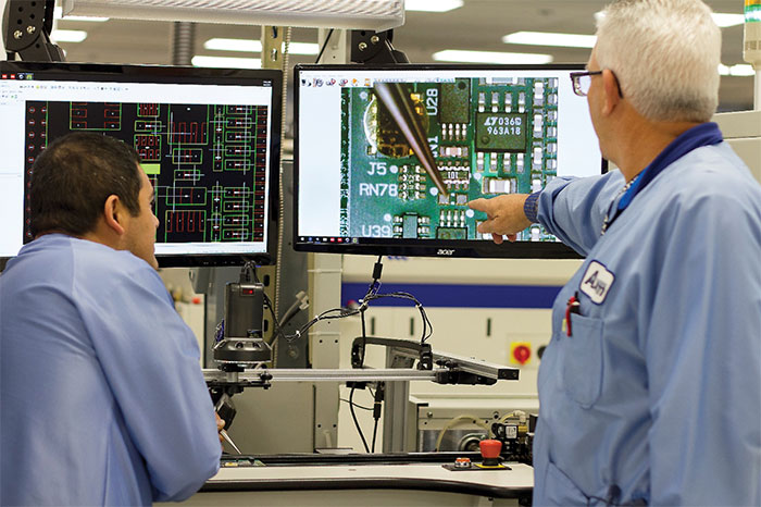
Figure 1. Engineers at Axiom use IPC-2581 data to assess inspection.
At Axiom, VisualCAM is used for preparation for assembly, and the WISE2581Viewer is used at each SMT machine and inspection station to visualize the board matches the actual assembly.
“The IPC-2581 file contains all the information I need for pick-and-place equipment and testing,” Pierce said. “Everything within that IPC-2581 file allows us to assemble, inspect and test PCB boards for our customers.”
Navigating IPC-2581. Users may not realize the amount of intelligence built into IPC-2581 files. This intelligence allows software vendors to support the various needs of end-users. For example, let’s peek in the Navigator in VisualCAM. It will show a detailed look at the data inside IPC-2581 files.
- Layers: shows the details on each layer (name, side, function, etc.)
- Apertures: shows details on all aperture (primitive) shapes used in the design
- Tools tables: all NC/drill/mill/slot/cavity tools used along with all sizes per table
- Nets: a complete list of nets included in the design; easily highlights and interrogates each net
- External nets: shows a complete list of physical net points and test points described in the file. These data can also be viewed on the PhyNet layer
- Layer sets: If multiple drill spans in the file, shows which layers are assigned to each layer set
- Assembly section gives access to detailed component/footprint/device information from a IPC-2581, file including reference designators, part names, part numbers, descriptions, footprint/device pins, side, assembly method (through-hole or SMT), whether to populate, etc. (FIGURE 2).
- Stackup: gives in-depth details of the IPC-2581 stackup including construction specifics and materials that define the finished board.
- BoM: the complete bill of materials required to build the board.
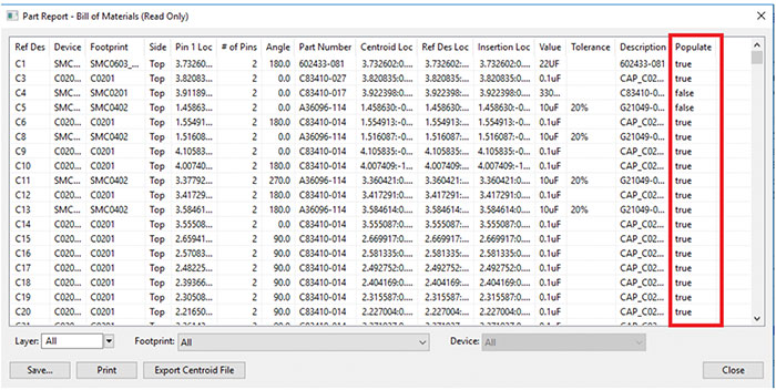
Figure 2. View and sort components in the BoM, including the populate status, and get the centroid data needed for assembly.
IPC-2581 also allows users to interrogate data with features like query by net name, component, footprint, device or part number, allowing a quick look inside the IPC-2581 file to find sought-after data.
This may seem like more information than needed, but it is important for intelligent, accurate and thorough processing of the data. Intelligent IPC-2581 formatted files not only enable software vendors to provide more-effective, robust solutions, they also ensure end-users a maximally streamlined process to reduce costs and increase quality.
BoM in IPC-2581. Having the BoM built into the IPC-2581 file allows users to indicate whether (or not) to insert (populate) each component during placement (FIGURE 3). Axiom can do this paperless by using the “populate” function in IPC-2581. Users can see what is included in the BoM, which parts are to be inserted, and which parts are not to be populated. This is extremely valuable during PCB assembly setup and at the placement machine to review data on screen in real time.
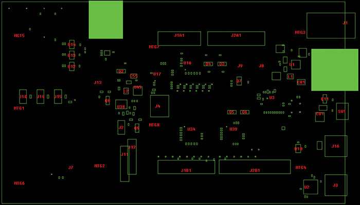
Figure 3. View assembly outlines as described in the IPC-2581 file on-screen. The filled areas make use of the “Populate” element in IPC-2581 to show parts not to be installed for ease of verification during assembly.
Axiom is able to manually set a “components populate” attribute value, or compare BoMs of different assemblies and update the BoM automatically to reset the populate setting in the file. Using features built into IPC-2581 enables assemblers to view these data in the BoM and graphically display on screen using VisualCAM or the WISE2581Viewer.
Test points. Test points are built inside the IPC-2581 file. Each pad has a “testpoint” attribute to indicate whether it is a candidate to be used for testing (FIGURE 4). With this feature built into IPC-2581 files, users can quickly see top and bottom test points onscreen by viewing the “IPC2581 PhyNet” layer. A user can further interrogate the data for detailed properties for each location, for instance, whether it is testable, middle point, exposed, fiducial, via, stagger radius, or if it’s a legal net short.
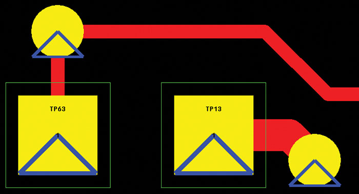
Figure 4. Each pad has a “testpoint” attribute to indicate the candidates for testing.
The PhyNet data are also used for netlist comparisons to ensure what is in the IPC-2581 file matches the graphic data on each individual layer. This provides assurance that the design is complete and correct.
Hole charts. Hole charts are easily created using the “Hole” element of the IPC-2581 file. This element describes the detailed characteristics of each hole, including name, diameter, plating status, tolerance, location and optional SpecRefs. This feature can display hole charts (FIGURE 5) and keep them on a drawing layer that stays with the IPC-2581 file.
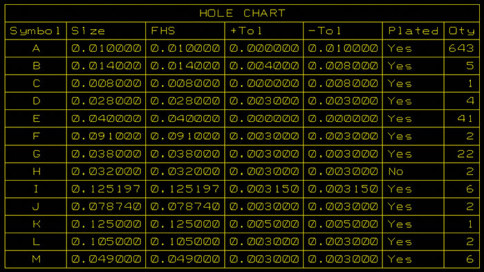
Figure 5. Sample hole chart.
Fabrication reports. Pushing for paperless, the information needed to manufacture a design can be visualized with the new fabrication reports. Look inside at the stackup with a graphic depiction, including the impedance, board information, designer notes, standard notes, and drill spans (FIGURE 6). Also included in the report are dimension drawing, hole chart, and assembly top and bottom. This new report allows further access to information inside the IPC-2581 file.
This quick tour of IPC-2581 today shows the significant progress made in capturing, maintaining, and augmenting the intelligent PCB data needed to produce low-cost, accurate and high-quality PCB assemblies. Users looking for an up-to-date format actively maintained to support today’s and tomorrow’s technologies have a solution today. To keep up with what is going on with IPC-2581, visit ipc2581.com and subscribe to the consortium’s newsletter.
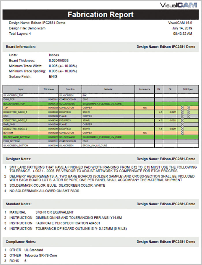
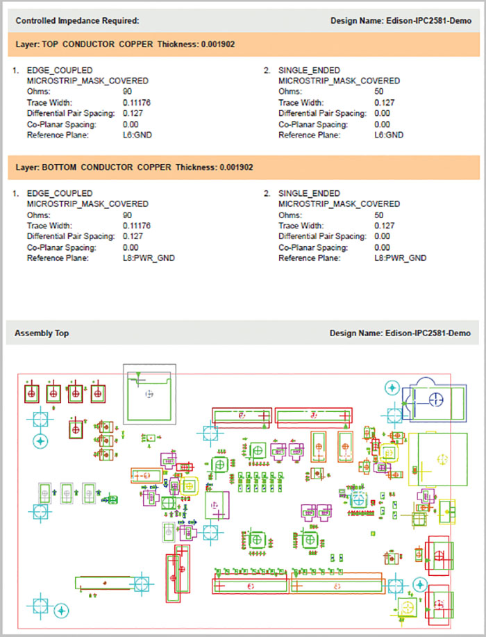
Figure 6. Sample fabrication report.
is vice president, WISE Software Solutions, Inc. (wssi.com); This email address is being protected from spambots. You need JavaScript enabled to view it..


