 Mitigation techniques and costs of designing around glass-weave skew.
Au: This column is a comprehensive follow-on to the July column introduction on glass-weave skew. With some overlap, these may be read together or independently.
In my July column, I introduced the causes of glass-weave skew (GWS) and when or why a hardware designer might care. In part two here, we discuss mitigation techniques and cost. In part three, we’ll do a deeper dive on the impact of glass styles on precipitating or mitigating skew.
While it is a real problem, it’s hard to characterize because it is statistical in nature. What is the chance one line in a pair will see a different dielectric constant than the other? It depends on the pitch of the lines, the length of the lines, the laminate composition, and the relative chance alignment of the glass bundles under the two lines.
Preventing Glass-Weave Skew
It would be nice if there were a simple, cost-free panacea for GWS, but almost all the remedies represent partial solutions that may work at some frequencies and line lengths, but not for others.
Here are some of the skew-control techniques, roughly ranked in ascending order of cost in manufacturing:
- Choose a glass style that minimizes resin windows.
- Choose a glass style with a “square weave” (equal number of yarn strands in the weave and fill directions).
- Route each member of the pair at the same pitch as the glass fibers.
- Align trace direction to the fill/weft.
- Use mechanically spread glass.
- Dual-ply glass
- Half weave pitch jog – halfway down the trace
- Zigzag routing of differential pairs at a 10º angle to the weave
- Build each PCB with the artwork rotated at a 10º angle to the panel and weave.
- Use glass with a lower dielectric constant (closer to the resin Dk).
Each of these carries a cost, either in terms of time, board space/material, or both. Before we elaborate on the aforementioned simple descriptions, the following observations are worth considering:
- No. 1-4 are essentially free.
- You may want to combine several of these techniques, particularly 1-6.
- If zigzagging the routing (8) or rotating board artwork (9), these approaches should be sufficient individually, but not in combination.
- You can also see significant reductions in skew with dual-ply (6), low-Dk (10) glass – individually or in combination – for example, but both approaches add to manufacturing cost. (Low Dk glass is roughly twice as expensive.)
Glass-based mitigation techniques (i.e., 1, 2, 5, 6, and 10) will be covered in more detail in part three. Here, we’ll primarily address routing and panelization techniques. But let’s first consider some basic principles regarding epoxy-glass (E-glass).
Glass Rotation
In theory, glass weaves run in a near-perfect x and y orientation. In practice, yarn wanders significantly. At DesignCon 2016, Bogatin et al presented findings that showed unintentional but almost inevitable glass rotation varied as much as +/-5º, relative to perfect x/y alignment, as shown in FIGURE 1.1 On one hand, this is helpful because it serves to “smear” the effect of Dk variation under a particular trace. On the other hand, it’s of no help at all because you can’t tell when or whether it’s going to happen. Nevertheless, it’s helpful to know the alignment variation at a general level, as it must be weighed when considering angled routing or artwork rotation at the panel level.

Figure 1. Unintentional but almost inevitable glass rotation varied as much as +/- 5º, relative to perfect x/y alignment.1
We also showed at DesignCon 2017 that only a half degree of angulation between the glass fabric and trace routing was enough to mitigate skew effects to a significant degree.2
While remembering the goal is to have the same number of glass-induced delays on both signals in a differential pair, the above two factors are important when considering rotation/angulation options. We’re looking for a predictable, consistent angle of more than 0.5º. Generally, the weft will tend to wander more than the weave, as the weave direction is in tension when resin is added and initial curing occurs. (For a definition of weft, read on.) Knowing the glass yarn itself may wander by as much as 5º in either direction, clockwise or counterclockwise, and the weft may wander more than the weave, becomes potentially important when seeking a predictably sufficient angle between the glass and differential-pair routing.
Glass and Panelization Terminology
Because of potential variation between glass yarn in the weave direction versus the weft, it’s important to know which is which. FIGURE 2 shows a slide from a class I teach at PCB West, providing an illustration of the glass-weaving process, as well as some of the underlying terminology. As shown, there are two primary yarn directions: the “machine” or “grain” direction, which we refer to as the weave, and the “cross” or “fill” direction, which we often refer to as the weft. “Grain” is an allegory to wood grain. Provided you know the synonyms, you’ll be able to align with counterparts while designing and building boards.

Figure 2. High-level glass-weaving process and terminology.3
So far, so good. Parts of this subject are easy to grasp. Others are a bit of a headache. In the headache column, the above glass roll results in rectangular rather than square sheets that can be cut with the long direction, parallel to the grain, or with the long sheet and panel dimensions parallel to the fill. North American PCB fabricators have been building boards with the long sheet and panel dimensions parallel to the grain (weave) for many years. (Some shops call this “long grain.”) In Asia, conversely, the norm is to build using glass with the weave running parallel to the short dimension of the rectangular sheets and panels, sometimes called “short grain.” So, for example, if you build prototypes in North America, and go to Asia for high-volume manufacturing, you may well be dealing with different glass orientation.
Some global fabricators with a North American presence have shifted to running PCBs with short sheet and panel dimensions parallel to the weave to match their higher-volume counterparts in Asia. While remembering the goal is to have the same number of glass-induced delays on both signals in a differential pair, the above two factors are important when considering rotation options. We’re looking for a predictable, consistent angle of more than 0.5°. Knowing that the glass itself may wander by as much as 5° in either direction, clockwise or counterclockwise, implies that whatever rotation strategies we employ should exceed 5.5°.
Panelization Options
Option 9 involves building each PCB with the artwork rotated at a 10º angle to the panel and weave. Some rotate the artwork as much as 12.5º, but that wastes more laminate material than is necessary to mitigate skew. A case can be made for rotating the artwork about 7.5º, and I’ve spoken to some who do that. I tend to recommend 10º artwork rotation, as it has plenty of margin relative to the 5º angle of some of the yarn strands, and it’s a relatively easy job for PCB layout software. Having said that, if someone argued for 7.5º, I wouldn’t disagree.
Rotated artwork, illustrated in FIGURE 3, is one of the more expensive options, but if you can absorb the cost of wasted material, it carries the advantage of essentially guaranteeing you won’t have glass-weave skew problems, provided you’re smart enough not to combine this approach with 10º angled routing, described below.
Figure 3. Board artwork rotated on a panel.4
Routing Options
Options 3, 4, 7 and 8 include routing each member of the pair at the same pitch as the glass fibers (3), aligning the trace direction to the fill/weft (4), making a half-weave-pitch jog halfway down the track (7), and zigzag routing of differential pairs at a 10º angle to the weave (8). Each of these will be discussed in turn below.
Option 3. Route each member of the pair at the same pitch as the glass fibers. Illustrated in FIGURE 4, this one warrants serious consideration as one of the essentially free options for mitigating glass-weave skew.
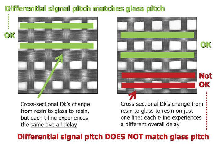
Figure 4. Pitch and fiber-weave effect (FWE). The green differential traces show that when differential-routing pitch matches the pitch of the adjacent glass, signal delays are equal. This is one of the simplest and lowest cost means of addressing GWS.
All glass styles have an inherent, IPC-4412B-specified yarn pitch in both the weave and fill directions. While these pitches aren’t typically published, it’s important to realize they’re a systematic component of each glass style.
If routing a differential pair on the nominal pitch of the glass, signal delays will be nominally symmetrical, which is exactly what you want! That this can be done at no additional expense makes me wonder why more designers don’t do it. Several new stackups cross my desk each week, and I always look for whether engineers and fabricators are taking advantage of this “freebie.” I don’t see it much, and I’ve been watching for some time.
There are some complications with this approach. If using a non-square weave – meaning the weave and the fill have different yarn counts – know the orientation of the board on a panel at the fabricator. It’s doable but requires some additional planning during layout.
Option 4. Aligning the trace direction to the fill/weft. As with #3, this one’s essentially free. The difference is it’s not a solution you can hang your hat on. It won’t hurt, but there’s no guarantee the additional, random wander of the weft is enough to address all the super-high-speed signal issues. On the plus side, this approach simply requires knowing how the board will be oriented to the manufacturing panels in production. In doing so, you’re gambling there’s enough wander in the weft to “smear out” some or most differences between the two differential signals. Logically speaking, it’s a standalone approach: There’s no logical reason to do this if you’re also rotating the board or the routing, or if you’re sure the signals are properly aligned to the glass pitch.
Option 7. Making a half-weave-pitch jog halfway down the trace. I’ve heard of this, but I haven’t seen it on an actual design. The idea is that half of a differential pair’s run length parallels the glass in one glass/Dk configuration, and the other half of the run length is “jogged” by half of the glass pitch. While I understand the theory, I can’t see any advantages for this approach over the much simpler practice of making the differential pair pitch equal to the glass pitch in the routing direction. Moreover, this approach assumes routing is only in one direction: the x or y. How often does that happen? For these reasons, I considered excluding this one, but mention it here just to poke holes in it, since I’ve seen it in at least one application note.
Option 8. Zigzag routing of differential pairs at a 10º angle to the weave. This approach consumes a bit of extra board space but has merit. For one thing, it’s an approach that is essentially guaranteed to work, doesn’t require tracking of glass pitch or panel orientation, and doesn’t require the sacrifice of unused panel space. Some engineers seem to bristle at the concept, but it absolutely works if the routing space can be allocated. As mentioned, a full 10º angle isn’t absolutely required, but I would recommend at least 7.5º.
This month we addressed routing and panelization techniques. Glass-based mitigation techniques (i.e., 1, 2, 5, 6 and 10) will be covered in more detail in part three.
Au note: If I could tell the industry there are known remedies for addressing an issue that would otherwise cripple their 2.5+ Gbps signals on a semi-random basis, I think the design world would beat a path to my door. I am interested in your comments if this article resonated. Or, feel free to download the evaluation software at z-zero.com that includes a tutorial for mitigating glass-weave skew.
References
1. Eric Bogatin, Bill Hargin, et al, “A New Characterization Technique for Glass Weave Skew Sensitivity,” DesignCon, January 2016.
2. Eric Bogatin, Bill Hargin, et al, “A New Characterization Technique for Glass Weave Skew (Part 2),” January 2017.
3. Bill Hargin, “PCB Stackup Design and Materials Selection,” PCB West, September 2018.
4. Jeff Loyer, et al, “Fiber Weave Effect: Practical Impact Analysis and Mitigation Strategies,” DesignCon, January 2007.
Bill Hargin has more than 20 years’ experience in PCB design software and materials. He is director of everything at Z-zero (z-zero.com); This email address is being protected from spambots. You need JavaScript enabled to view it.. He is speaking at PCB West in September.


